Yokogawa Data Acquisition with PID Control CX2000 User Manual
Page 123
2-6
IM 04L31A01-01E
LOOP2
2
1
3
2
1
PV
PV
(RSP)
(RSP)
(RSP)
(RSP)
PV
PV
PV1
PV1
PV2
PV2
LOOP1
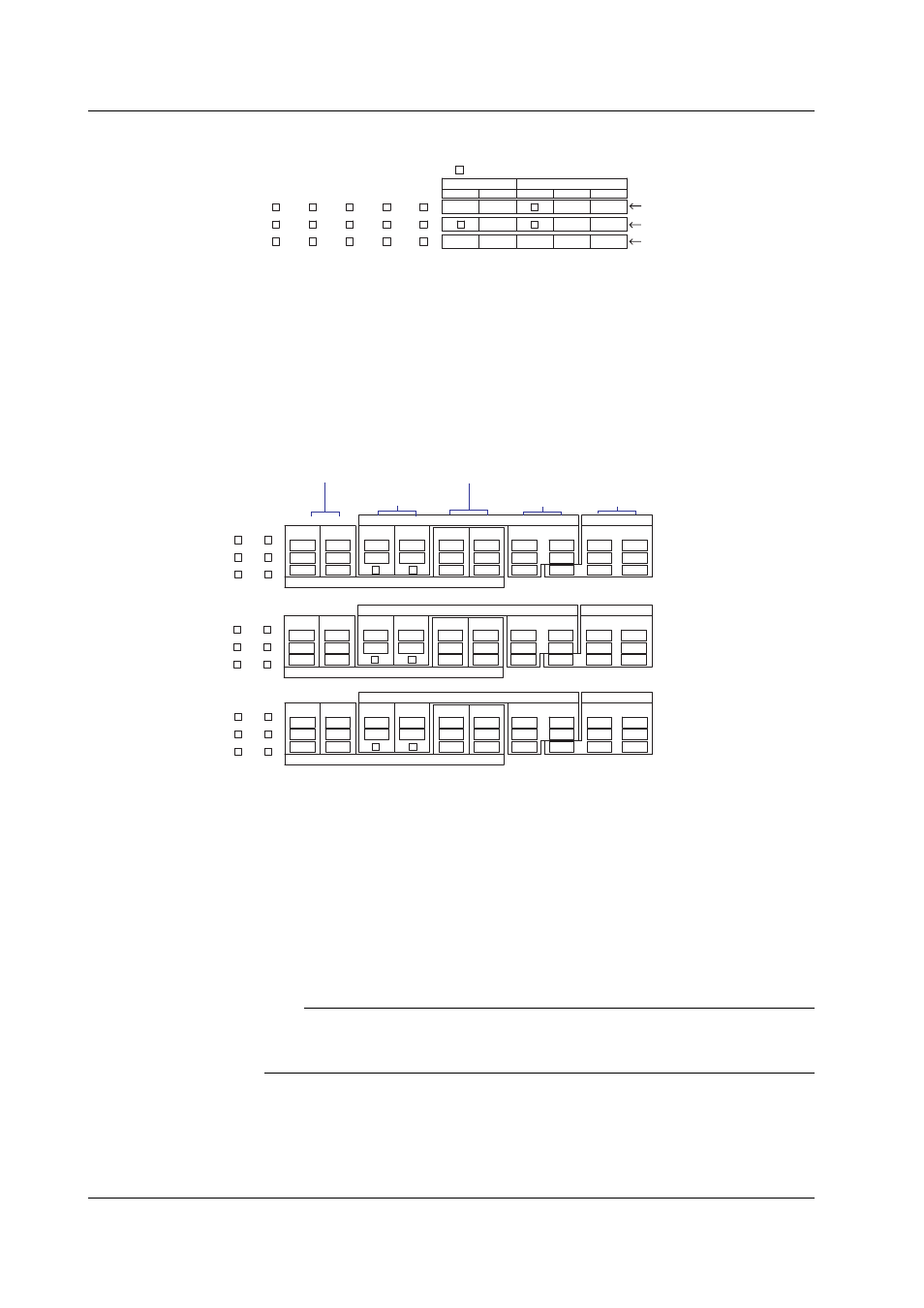
• 2 loops
PV, PV1, PV2: PV input, (RSP): RSP input
(not used during program control), : unused terminal
During single-loop control
During cascade control
During loop control with
PV switching
[Control mode setting]
When PV/SP is ON, the numbers CI01, CI02, CI03, CI04, CI05, CI06, CI07, CI08, CI09,
and CI10 are assigned to each control input terminal starting on the right as you face the
terminals, and the PV/SP of each loop is the computed value.
Terminal Arrangements of the Control Output Terminal Block
Each block has a control output containing 2 loops of current output, voltage pulse
output, and relay contact output terminals, 6 contact input, 2 relay contact output, and 4
transistor output terminals. The following figure shows their arrangement. Wire the
terminals according to the configuration.
LOOP1
NO
NC
C
NO
C
2
NO
NC
C
LOOP2
CTRL OUT
mA
PULS
C
LOOP2
mA
PULS
C
C
5
6
C
3
4
4
5
6
1
2
3
LOOP1
CTRL OUT
DIGITAL OUT
DIGITAL OUT
DIGITAL IN
NO
C
1
LOOP3
NO
NC
C
NO
C
2
NO
NC
C
LOOP4
CTRL OUT
mA
PULS
C
LOOP4
mA
PULS
C
C
C
4
5
6
1
2
3
LOOP3
CTRL OUT
DIGITAL IN
NO
C
1
LOOP5
NO
NC
C
NO
C
2
NO
NC
C
LOOP6
CTRL OUT
mA
PULS
C
LOOP6
mA
PULS
C
C
C
4
5
6
1
2
3
LOOP5
CTRL OUT
DIGITAL IN
NO
C
1
DIGITAL OUT
DIGITAL OUT
DIGITAL OUT
DIGITAL OUT
• For loops
1 and 2
• For loops
3 and 4
• For loops
5 and 6
Control power supply
voltage pulse output
Contact
input
Transistor
output
Relay contact
output
Control relay
contact output
C: Common
NO: Normally
Opened
NC: Normally
Closed
mA: Current
output
PULS: Voltage pulse output
5
6
3
4
5
6
3
4
[DIGITAL OUT] terminals 1 to 6 are indicated using the following numbers when the
control output terminal block is selected in the contact (relay) output registration setting
or alarm relay output setting.
• DO001 to DO006 (Contact output of the loop 1 and 2 control output terminal block [CTRL1-2])
• DO101 to DO106 (Contact output of the loop 3 and 4 control output terminal block [CTRL3-4])
• DO201 to DO206 (Contact output of the loop 5 and 6 control output terminal block [CTRL5-6])
In addition, [DIGITAL IN] terminals 1 to 6 are indicated using the following numbers when
the control output terminal block is selected in the contact input registration setting.
• DI001 to DI006 (Contact output of the loop 1 and 2 control output terminal block [CTRL1-2])
• DI101 to DI106 (Contact output of the loop 3 and 4 control output terminal block [CTRL3-4])
• DI201 to DI206 (Contact output of the loop 5 and 6 control output terminal block [CTRL5-6])
Note
In the contact (relay) output setting, relay contact outputs DO001, DO002, DO101, DO102,
DO201, and DO202 and the numbers of transistor outputs are not distinguished. Confirm this
before registering the output signals.
2.3 Wiring