Yokogawa Data Acquisition with PID Control CX2000 User Manual
Page 347
13-3
IM 04L31A01-01E
Maintenance
13
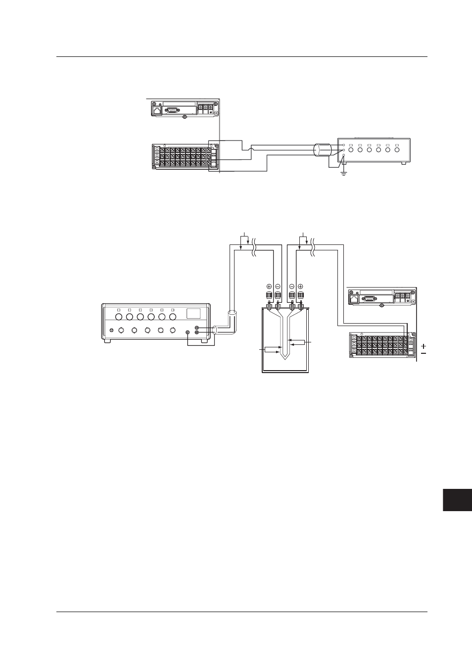
Temperature Measurement When Using an RTD
The resistance of three lead
wires must be equal.
+/A
-/B
/b
L
N
Input terminals
b
A
B
Decade resistance box
(Model 2793-01 from
Yokogawa M&C)
Power supply
terminals
Temperature Measurement When Using a thermocouple
L
N
+
-
+
-
Copper wire
Thermocouple wires or TC estension wire
DC voltage standard
(0°C standard temperature device: Model ZC-114/ZA-10 from Coper Electronics Co., Ltd.)
Input terminals
Power supply terminals
Thermocouple
wire
Copper
wire
Cold junction
Reference Junction Compensation of Thermocouple Input
As the measurement terminal of the CX2000 is generally at room temperature, the actual
output of the thermocouple is different from the values given on the thermoelectromotive
force table based on 0°C. The CX2000 performs compensation by measuring the
temperature at the input terminal and adding the corresponding thermoelectromotive
force to the actual output of the thermocouple. Therefore, when the measurement
terminal is shorted (equivalent the detector tip being 0°C), the measured value indicates
the temperature of the input terminal.
When calibrating the CX2000, this compensation voltage (thermoelectromotive force of 0
°C reference corresponding to the input terminal temperature) must be subtracted from
the output of the standard generator before application. As shown in the figure, by using
the 0 °C standard temperature device to compensate the reference junction at 0°C, you
can input the thermoelectromotive force of 0°C reference from the DC voltage standard
and perform the calibration.
13.2 Calibration