Control output terminal, Installation and wiring, 3 wiring – Yokogawa Data Acquisition with PID Control CX2000 User Manual
Page 130
2-13
IM 04L31A01-01E
Installation and Wiring
3
2
1
4
5
6
7
8
9
10
11
12
13
14
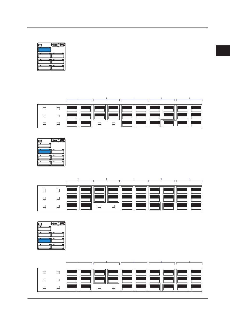
Control Output Terminal
Control Output Terminals for Loops 1 and 2
VIDEO OUT(VGA)
L N
Symbols
NO: Normally opened, NC: Normally closed, C: Common
mA: Current output, PULSE: Voltage pulse output
Contact input
Transistor output
Control current output/
voltage pulse output
Relay
contact output
LOOP1
LOOP2
1
Control relay
contact output
LOOP1
LOOP2
2
325
326
327
328
329
330
322
323
319
320
316
317
318
313
314
315
310
311
312
307
308
309
304
305
306
4
5
6
3
4
C
5
6
C
mA
PULSE
C
mA
PULSE
C
NO
C
NO
C
NO
NC
C
NO
NC
C
1
2
3
301
302
303
Control Output Terminals for Loops 3 and 4
VIDEO OUT(VGA)
L N
LOOP3
LOOP4
1
LOOP3
LOOP4
2
425
426
427
428
429
430
422
423
419
420
416
417
418
413
414
415
410
411
412
3407
408
409
404
405
406
4
5
6
3
4
C
5
6
C
mA
PULSE
C
mA
PULSE
C
NO
C
NO
C
NO
NC
C
NO
NC
C
1
2
3
401
402
403
Contact input
Transistor output
Control current output/
voltage pulse output
Relay
contact output
Control relay
contact output
Control Output Terminals for Loops 5 and 6
VIDEO OUT(VGA)
L N
LOOP5
LOOP6
1
LOOP5
LOOP6
2
525
526
527
528
529
530
522
523
519
520
516
517
518
513
514
515
510
511
512
5407
508
509
504
505
506
4
5
6
3
4
C
5
6
C
mA
PULSE
C
mA
PULSE
C
NO
C
NO
C
NO
NC
C
NO
NC
C
1
2
3
501
502
503
Contact input
Transistor output
Control current output/
voltage pulse output
Relay
contact output
Control relay
contact output
2.3 Wiring