Yokogawa Data Acquisition with PID Control CX2000 User Manual
Page 274
8-17
IM 04L31A01-01E
Operations for Changing the Displayed Contents
8
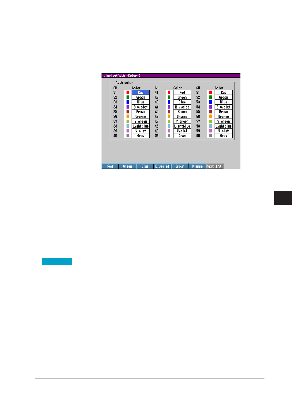
• Colors of computation channels
Press the keys in the following sequence:
MENU key
(switch to setting mode(control)) >
MENU key
(switch to thetmode) >
#4 soft key
(select [Display]) >
#7 soft key
(select [Math(Color)])
The following display appears.
Setup Procedure
1. Use the
arrow keys
to move the cursor (blue) to the [Color] box of the channel you
wish to change.
A soft key menu used to select the color appears at the bottom of the display.
On the [Control(Color)] display, you must select the control loop using the [Select]
box before this step.
2. Press the
soft key
corresponding to the color you wish to select.
The box for the item you changed turns yellow, and the cursor moves to the next
item.
3. Repeat steps 1 and 2 to set all the colors you wish.
4. Press the
DISP/ENTER key
to confirm the changes.
The boxes for the items you changed turn from yellow to white, and the cursor
returns to the first item.
Setup Items
Setting the Channel Color
• Select
(Only when assigning channels of PV, SP, and OUT of control)
Select the group of the control loop you wish to set the color from [Internal], [Ext1],
[Ext2], and [Ext3]. The channel assignment of each group is displayed under the
[Select] box. For example, [201 L01PV] indicates that the channel number is [201]
and the external loop number is [01].
• Color
The colors are initially set in the following order for every 9 channels. However, if the
number of measurement channels is 10, channel 10 is gray.
1: Red, 2: Green, 3: Blue, 4: Blue violet, 5: Brown, 6: Orange:, 7: Yellow green, 8:
Light blue, and 9: Violet.
To change the color select from the following 16 colors.
Red, green, blue, blue violet, brown, orange, yellow-green, light blue, violet, gray,
lime, cyan, dark blue, yellow, light gray, and purple.
8.11 Measurement Function > Changing the Channel Display Color