Yokogawa Data Acquisition with PID Control CX2000 User Manual
Page 19
1-7
IM 04L31A01-01E
Explanation of Functions
3
2
1
4
5
6
7
8
9
10
11
12
13
14
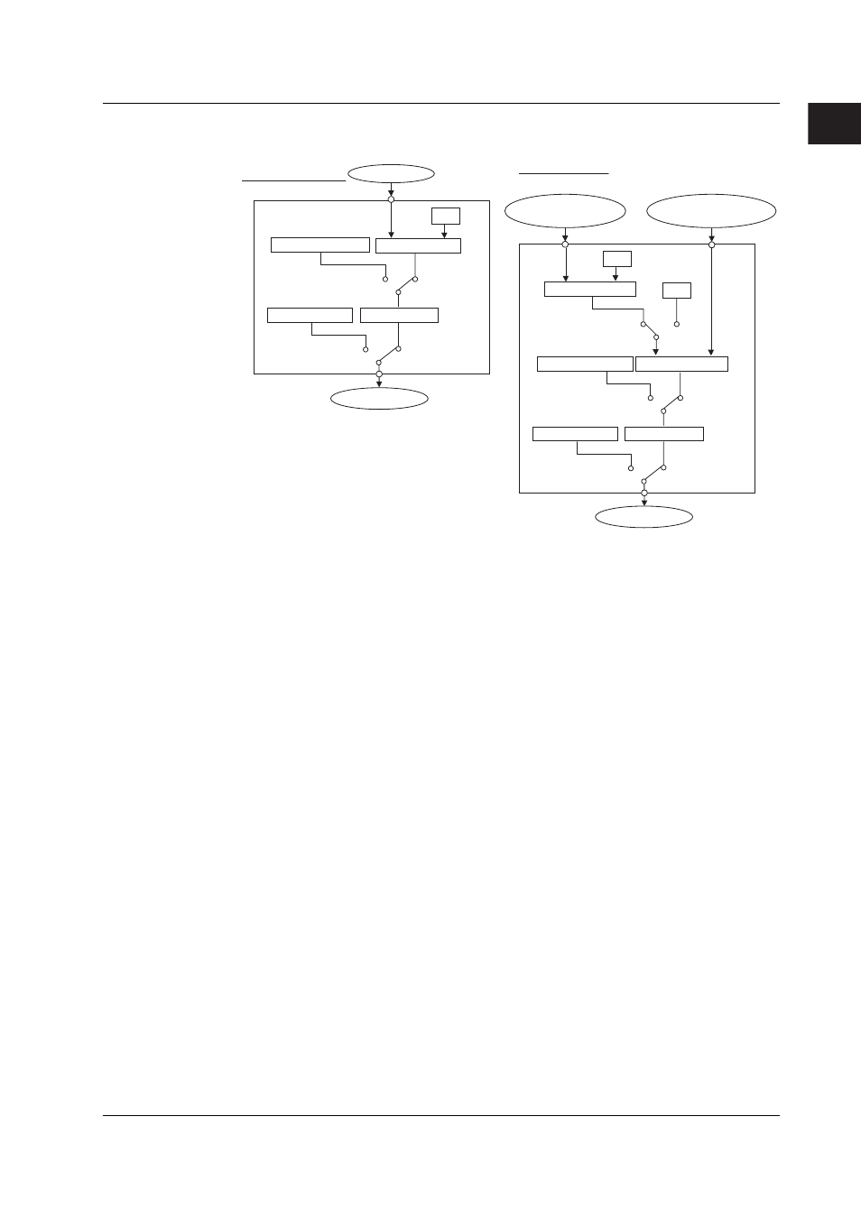
Switching between Run (RUN) and Stop (STP)
When the operation is stopped, the control output value (OUT) is set to the preset value.
PV input
SP
Controller CPU
Manual operation
Output limiter
Preset output
Auto (AUT)
Manual (MAN)
Run (RUN)
Stop (STP)
PV
Single-loop control
Control output
OUT
PV input 1
(Cascade primary)
Control output
Controller CPU 1
SP1
PV input 2
(Cascade secondary)
SP2
Controller CPU 2
Manual operation
Output limiter
Preset output
Cascade
Auto/
Manual
Cascade/
Auto
(CAS/AUT)
Manual (MAN)
Run (RUN)
Stop (STP)
PV1
PV2
OUT
Cascade control
Enabling/Disabling Auto-Tuning
In PID control, the optimum PID constant is set automatically when auto-tuning (see
page 1-52
) is performed. Auto-tuning is possible only during auto operation.
Contact Input
Contact input can be used to carry out operations such as running/stopping operation,
switching operation modes, changing SPs, switching PV inputs (during loop control with
PV switching). For a description on the possible operations, see “Contact Input
Information Registration” on page 1-24.
PV/SP Computation (Style Number S3 or Later)
You can use the specified computed result as PV or SP. When PV/SP computation is
ON, you can set the control analog input terminals to CI01-CI10, and set the range for
each channel.
The SP is active when the control operation mode is Remote. You can also use the
control output value in the equation. The constants that can be used are separate from
the computation function (W01-W36). When a computation error occurs, you can treat
the computed result as an overrange or underrange. Computation is performed in
synchronization with the control interval.
1.2 Control Function Overview