Loop control with pv switching (program control), Analog retransmission – Yokogawa Data Acquisition with PID Control CX2000 User Manual
Page 414
App-45
IM 04L31A01-01E
Appendix
App
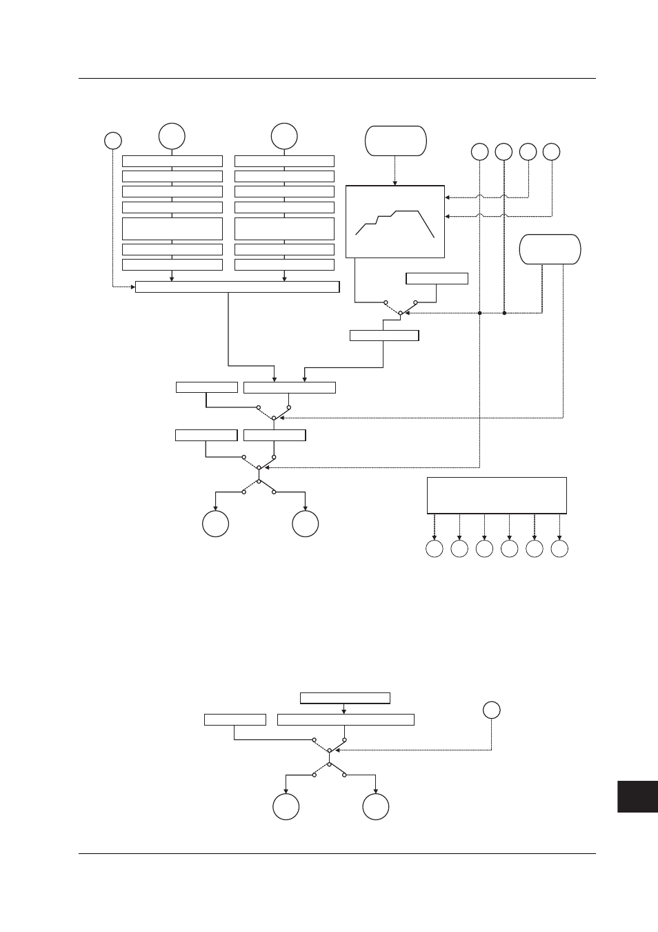
Loop Control with PV Switching (Program Control)
PV
input
1
Contact input
Loop control with PV switching
PV switching
PV
input
2
Control computation section
Manual operation
Preset output
Current or
pulse
Relay
Run
Auto
Manual
Stop
Output limiter
DI
DI
3
DI
DI
DI
Control output
SP ramp-rate setting
SP 1 to 8
Local
Local switching
Program
Program pattern selection
Program operation
Hold operation start
Advance operation start
Program operation stop
Program operation start
Note: Does not function
during program
control
Input type selection
Unit selection
Analog input range conversion
Square root computation
Ten-segment linearizer approx.
ten-segment linearizer bias
PV input bias
PV input filter
Input type selection
Unit selection
Analog input range conversion
Square root computation
Ten-segment linearizer approx.
ten-segment linearizer bias
PV input bias
PV input filter
Expansion
contact
input
Expansion
contact
input
Time
event
1
Time
event
2
Meas.
alarm
1
Meas.
alarm
2
PV event output
Time event output
Measurement alarm function
PV
event
1
PV
event
2
DO
DO
DO
DO
DO
DO
Note: There are 6 contact input terminals and
6 contact output terminals on a single
control output terminal block.
The functions that can be assigned to
each input/output terminal vary depending
on the control mode and whether program
operation is enabled.
Analog Retransmission
Contact input
DI
Analog retransmission computatin section
Control measurement data
Manual operation
Current or
pulse
Relay
Auto
Manual
Control output
Appendix 7 Control Functon Blodk Diagram