3 basic settings of control, Basic settings of control -16 – Yokogawa Data Acquisition with PID Control CX2000 User Manual
Page 28
1-16
IM 04L31A01-01E
1.3
Basic Settings of Control
PID Group Number
You can set up to eight groups of control parameters (“PID parameters” on the setting
display) that you wish to change collectively through control. You set the number of groups
to be used from 1 to 8. For example, if you set a value of 4, the selectable PID numbers
will be 1 through 4. The parameters that are included in a single control parameter group
vary depending on the control method (“Control output” in the settings).
During PID control:
SP, PID constant, output lower/upper limit, shutdown ON/OFF (only
when outputting 4-20 mA of current), manual reset, reverse/direct, and
preset output
During ON/OFF control: SP, relay hysteresis, reverse/direct, and preset output
Control Period
The following control periods can be selected:
250 ms (initial value), 500 ms, and 1 s.
The control period is common to all loops. When the A/D integral time is set to 100 ms,
the control period is fixed to 1 s.
The scan interval of control PV input is the same as the control period.
PID Selection Method (Zone PID ON/OFF)
Select either one from below. When program control is ON on models with the program
control option, the selection is between the segment PID method (zone PID OFF) and
the zone PID method.
• Target setpoint selection method (zone PID: OFF) (initial value)
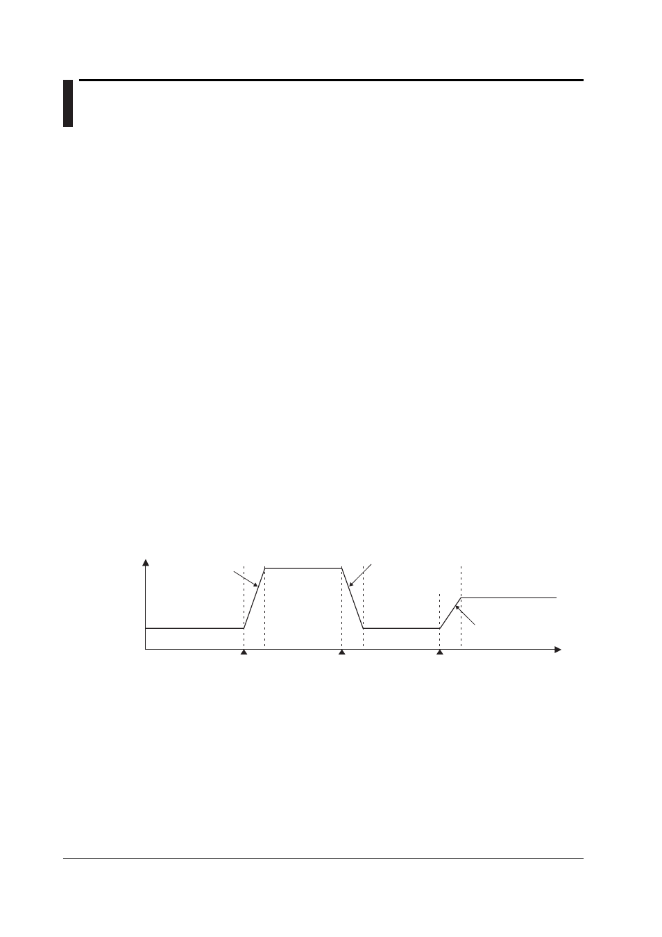
In the target setpoint selection method, the operator can switch up to 8 SPs as necessary.
There are two methods in switching the SPs. One method is to specify the SP number (SPs
are registered to PID numbers (= SP numbers) along with PID constants and other
parameters) using keys on the front panel. The other is to use external contact input or
communications. The SP can be switched at any time. During switching, the setpoint ramp-
up-rate or setpoint ramp-down-rate setting is activated. In addition, when a switch is made,
control computation is performed using the PID constant group that corresponds to the SP at
that point.
SP1
(No.1 PID)
SP3
(No.3PID)
SP1
(No.1 PID)
SP2
(No.2PID)
PV
Rise according to
the setpoint
ramp-up setting
SPn: SP number
Rise according to the
setpoint ramp-up setting
Switch from SP1 to SP3
Switch from SP3 to SP1 Switch from SP1 to SP2
Time
Fall according to
the setpoint
ramp-down setting
• Zone PID method
In the zone PID method, the measurement span is divided into a maximum of seven zones
using reference points. The optimum PID constant is preassigned to each zone, and the
PID constant (in actuality, other control parameters that are registered using the PID
number are included) is automatically switched according to the PV.
The number of reference points that can be specified is “PID group number – 2.” As shown in
the figure on the next page, if the PID group number is 7, the number of reference points is 5.
If the number of reference points is 5, there are 6 zones. For example, if zones 1 through 6
correspond to PID numbers 1 through 6 and if the PV is within the zones of reference points 3
and 4, the control parameters of PID number 4 are selected. The control parameters of PID
number 7, which cannot be assigned to a zone, are selected when the deviation between the
SP and PV becomes greater than the preset reference deviation.