Chapter 1 explanation of functions, 1 cx2000 overview, Cx2000 overview -1 – Yokogawa Data Acquisition with PID Control CX2000 User Manual
Page 13: Cx2000
1-1
IM 04L31A01-01E
Explanation of Functions
3
2
1
4
5
6
7
8
9
10
11
12
13
14
1.1
CX2000 Overview
The CX2000 consists of a control function and a measurement function. The control
function executes control through PID control and ON/OFF control. The measurement
function displays and acquires measured data and control-output data.
Control Function
The CX2000 supports thee control modes: single-loop control, cascade control, and loop
control with PV switching or analog Retransmission. It can handle up to six loops of PID
control. In addition, the UT Series controllers made by Yokogawa M&C Corporation can
be connected and controlled simultaneously as external loops (16 loops max.). You can
check the control status on the controller style and faceplate style displays and the
hybrid style display that is a mixture of the two styles. Furthermore, the overview display
allows monitoring of all control loops including external loops. In addition, the CX2000
provides auto-tuning of PID constants as well as manual tuning, which enables you to
adjust the control parameters such as PID constants while checking the control status.
Measurement Function
In addition to the measured data for the control function, the CX2000 can acquire up to
20 channels of measured data. The data can be displayed as waveforms, numeric
values, and bar graphs. The measured data along with the control data can be stored to
a floppy disk, Zip disk, or ATA flash memory card using the built-in drive.
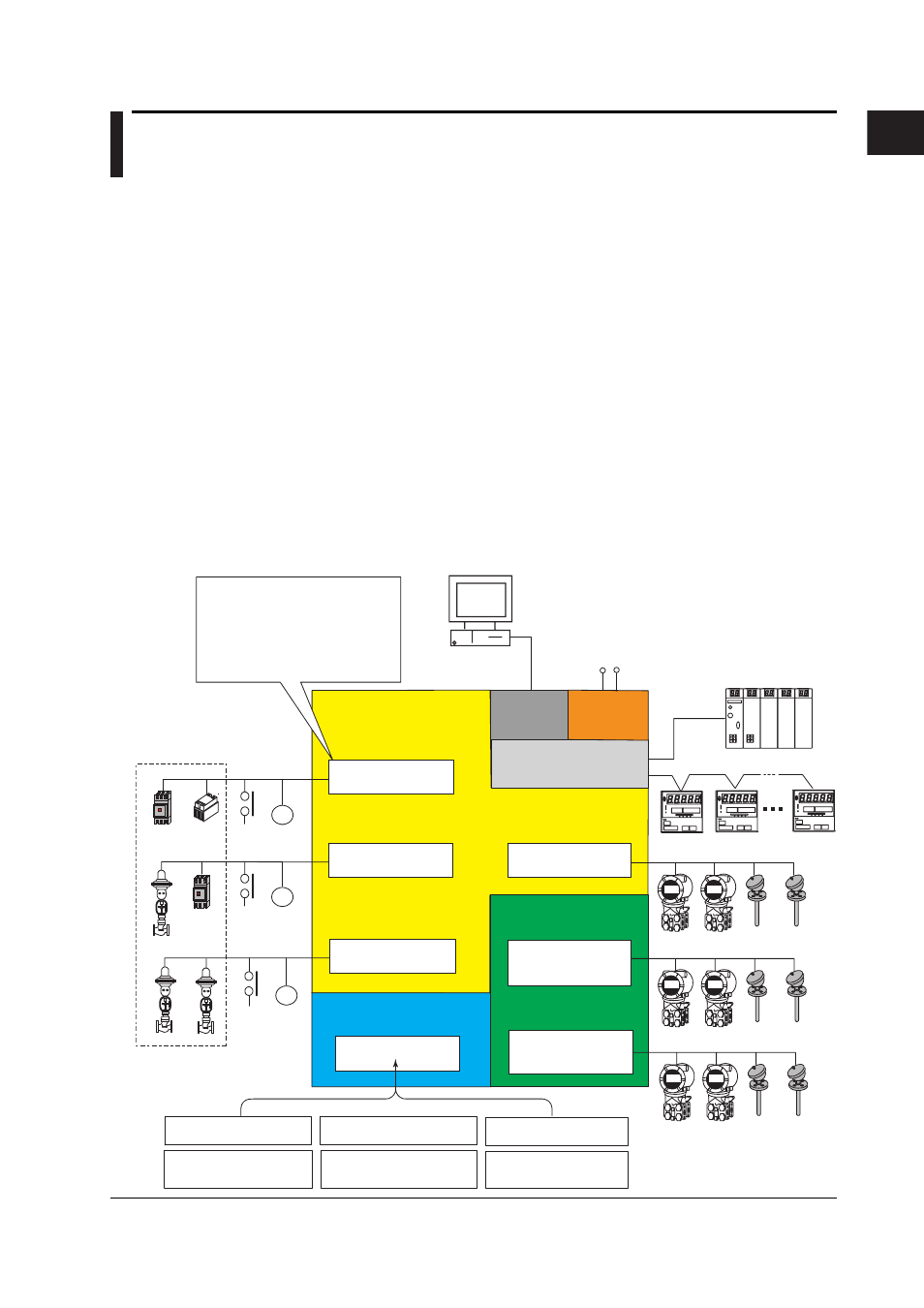
Conceptual Input/Output Diagram
Control input terminal
block 1
Control loop section
Up to 6 loops
(select 0, 2, 4, or 6 loops)
Measurement input
section
(10CH/20CH)
Ethernet
Controllers (up to 16 loops)
10 universal measurement inputs
100 VAC to 240 VAC or
24VDC/AC (P1 option)
SSR
• Universal control output: for 2 loops
Select current, voltage pulse, or relay
output.
LAN (Ethernet)
R3
R2
R1
Power
Supply
10 universal measurement inputs
10 universal measurement inputs
Option input/output
section
Select one from the following option terminal blocks.
Measurement alarm output +
remote input/output
(/A6R option)
Four 24-VDC transmitter
power supplies
(/TPS4 option)
Control DIO expansion
(/CST1 option)
PLC
(such as the FA-M3
by YOKOGAWA)
PC
Controls and
switches
CX2000
Measurement alarm output +
FAIL/memory end output
(/A4F option)
Measurement alarm output +
FAIL/memory end output +
remote input/output
(/A4FR option)
• Control contact input: 6 inputs
• Control contact input
Relay output: 2 outputs
Transistor output: 4 outputs
Magnet
switch
Contact
input
6 inputs
Contact
output
6 outputs
Control output terminal
block 1 (Loops 1 and 2)
Control output terminal
block 2 (Loops 3 and 4)
Control output terminal
block 3 (Loops 5 and 6)
Magnet
switch
Contact
input
6 inputs
Contact
output
6 outputs
Contact
input
6 inputs
Contact
output
6 outputs
Serial interface port
RS-422/485/232
Measurement input
terminal block 1
CH1 to CH10
Measurement input
terminal block 2
CH11 to CH20
Measurement alarm output
(/A6 option)
Chapter 1 Explanation of Functions