2 control function overview, Control function overview -2, Control signal input/output – Yokogawa Data Acquisition with PID Control CX2000 User Manual
Page 14
1-2
IM 04L31A01-01E
1.2
Control Function Overview
Control Signal Input/Output
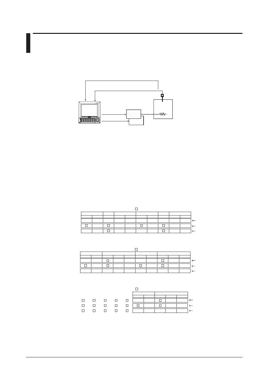
As shown in the following figure, the CX2000 can control up to six loops (up to four or
two loops on the 4- or dual-loop models, respectively).
CX
Scanner
• TC
• RTD
etc.
Control PV input
(number of analog inputs: 10)
Control output
Object of
control
• SSR
• Magnet switch
etc.
[Up to 6 loops]
• Relay
• Voltage pulse
• Current
··
·
··
·
The UT Series controllers made by Yokogawa M&C Corporation can be connected via
the serial interface and controlled simultaneously as external loops (16 loops max.) (see
the DAQSTATION CX1000/CX2000 Communication Interface User’s Manual).
Analog Input for Loop Control
PV input and remote setpoint input (RSP) are available as control signal inputs. You can
select thermocouple, resistance temperature detector, standard signal, or DC voltage for
both PV input and RSP input. The RSP input is used as a terget setpoint (SP). There
are 10 input terminals on the control input terminal block (5 input terminals for dual loop).
When PV/SP computation is OFF, each input terminal is assigned depending on the
number of loops used and the control mode (see next page) as shown in the figure below.
LOOP1
2
1
PV
(RSP)
(RSP)
PV
PV1
PV2
LOOP2
LOOP5
LOOP6
2
1
PV
1
PV
1
PV
(RSP)
PV
PV1
PV2
LOOP3
2
1
PV
(RSP)
(RSP)
PV
PV1
PV2
LOOP4
2
1
PV
(RSP)
PV
PV1
PV2
During single-loop control
During cascade control
During loop control with
PV switching
[Control mode setting]
• 6 loops
PV, PV1, PV2: PV input, (RSP): RSP input
(not used during program control), : unused terminal
LOOP4
LOOP3
LOOP2
LOOP1
2
1
3
2
1
3
2
1
2
1
PV
PV
(RSP)
(RSP)
(RSP)
(RSP)
PV
PV
PV1
PV1
PV2
PV2
PV
PV
(RSP)
(RSP)
(RSP)
(RSP)
PV
PV
PV1
PV1
PV2
PV2
• 4 loops
PV, PV1, PV2: PV input, (RSP): RSP input
(not used during program control), : unused terminal
During single-loop control
During cascade control
During loop control with
PV switching
[Control mode setting]
LOOP2
2
1
3
2
1
PV
PV
(RSP)
(RSP)
(RSP)
(RSP)
PV
PV
PV1
PV1
PV2
PV2
LOOP1
• 2 loops
PV, PV1, PV2: PV input, (RSP): RSP input
(not used during program control), : unused terminal
During single-loop control
During cascade control
During loop control with
PV switching
[Control mode setting]
When PV/SP is ON, the numbers CI01, CI02, CI03, CI04, CI05, CI06, CI07, CI08, CI09,
and CI010 are assigned to each control input terminal starting on the right as you face
the terminals, and the PV/SP of each loop is the computed value.
You can apply scale conversion, bias, input filter, ten-segment linearizer bias, ten-
segment linearizer approximation, and square-root computation on the control signal
input. For thermocouple inputs, you can set reference junction compensation. In
addition, ratio setting can be specified against RSP inputs.