Yokogawa Data Acquisition with PID Control CX2000 User Manual
Page 207
4-47
IM 04L31A01-01E
Control Function Related Setup Operations
4
4.19 Settings for Switching the Program Patterns
Using Contact Inputs with BCD Codes (Version
3.20 or Later)
In addition to the binary representation that was conventionally used to specify the
program pattern number when the program pattern was switched using contact inputs, a
way of specifying the program pattern using binary-coded decimal (BCD) representation
has been added.
Bits Used When Specifying the Program Pattern Number Using BCD Code
Program Pattern
Number Used
Bit 5
Bit 4
Bit 3
Bit 2
Bit 1
Bit 0
✔
✔
✔
✔
✔
✔
✔
✔
✔
✔
✔
✔
✔
✔
✔
✔
✔
✔
✔
✔
✔
Pattern Number Designation Bit
1
Up to 3
Up to 7
Up to 9
Up to 19
Up to 30
10’s digit
1’s digit
For example, set [PatternNo1bit] and [PatternNo4bit] to ON (10010) to specify pattern
number [12]. Contact inputs that can be registered to [PatternNo0bit] to [PatternNo5bit]
are [DI001 to DI006], [DI101 to DI106], and [DI201 to DI206] of the control output
terminal block and [RI001 to RI006] of the control expansion DIO terminal block.
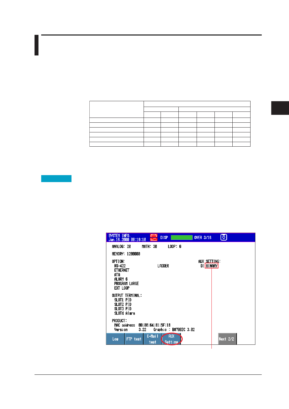
Procedure
Switching between BCD and Binary
Use the soft keys on the system information display to switch between binary and BCD.
You cannot make the switch during control operation, during data acquisition to the
internal memory, or during computation (the [Aux Setting] soft key below does not
appear).
• Switching from Binary to BCD
1.
FUNC key
>
[Log] soft key
>
[System] soft key
(switch to SYSTEM INFO.
display) >
FUNC key
>
[AUX Setting] soft key
Displays the current setting
(BINARY or BCD)