Yokogawa Data Acquisition with PID Control CX2000 User Manual
Page 236
6-11
IM 04L31A01-01E
Operations during Control Operation
6
Setup Items
Manual Tuning
Set the parameters to be tuned using [Control] > [Turning setting]. For the procedure,
see section 4.5, “Control > Tuning setting.”
The initial settings of the tuning parameters are shown below. The numbers indicate the
order of items on the tuning display starting from the upper left corner. The characters
indicate the item names (tuning parameter name). In addition to the tuning parameters
below, [DR] (control direction) and [H] (relay hysteresis) are available. For external loops
using Green Series communications, [DB] (dead band) is also available.
01: SP (target setpoint)
08: D (derivative time)
15: Off
02: A1 (alarm value1)
09: OH (output high-limit)
16: Off
03: A2 (alarm value 2)
10: OL (output low-limit)
17: Off
04: A3 (alarm value 3)
11: MR (manual reset)
18: Off
05: A4 (alarm value 4)
12: PO (preset output)
19: Off
06: P (proportional band)
13: Off
20: Off
07: I (integral time)
14: Off
21: Off
Display and Operation on the Tuning Display and Control Mode
For internal loops, the possible operations that you can perform on the tuning display
vary depending on the control mode.
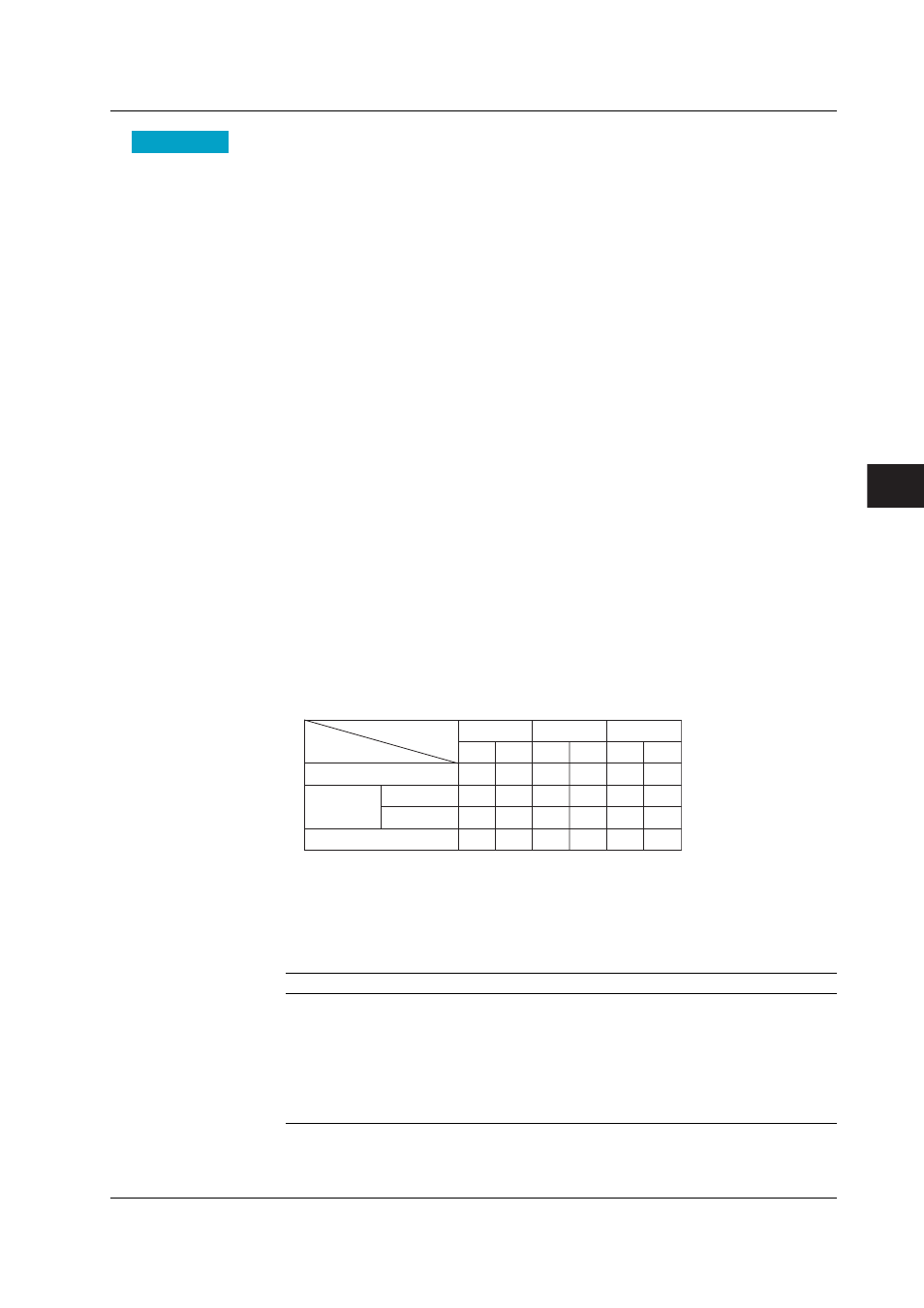
The table below shows the relationship between the display/operations specific to the
tuning display and the control mode. For the relationship between the display/operations
that are common with the control display and the control mode, see “Display and
Operation on the Control Display and Control Mode” on page 6-6. For a description on
the “display/operations and control mode” of external loops through the optional Green
series communications, see the DAQSTATION CX1000/CX2000 Communication
Interface User’s Manual
.
AT: Execute auto tuning
SP NO.: Switch the SP number
Group NO.: Switch the PID number of the tuning parameter to be manipulated
Dsp.
Yes
Yes
Yes
Yes
Opr.
Yes*
Yes*
Yes*
Yes*
Opr.
Yes
Yes
Yes
Yes
Control mode
Display/Operation
Type
Single loop
Cascade
PV switching
Primary
Secondary
Dsp.
Yes
Yes
Yes
Yes
Dsp.
Yes
Yes
Yes
Yes
Opr.
Yes
Yes
Yes
Yes
AT
SP NO.
GROUP NO.
* Not displayed in the soft key menu if [Control] > [#1 Control
action, Input setting] > [Auto tuning] is set to [OFF].
In addition, there are conditions in which certain soft keys appear, but their operation is not
possible. The table below shows the conditions and corrective action specific to the tuning
display. For the conditions and corrective actions that are common with the control display,
see “Display and Operation on the Control Display and Control Mode” on page 6-6.
Condition in Which Operation Is Not Possible
Corrective Action
When auto tuning is already in progress
Abort the auto tuning operation in
progress.
Mode other than auto operation mode and loop other than
Switch the auto operation mode
the primary loop of cascade control
Primary loop of cascade control and the secondary loop
Switch to cascade mode
are not set to cascade mode
Operation stopped
Start the Operation
When “A/D error” or “burnout error” occurs at the input.
Resolve the cause of the error
• Error messages for the operations above
When auto tuning is in progress: Auto-tuning is activated already.
Others: Auto-tuning cannot be activated.
6.3 Tuning Operation