Yokogawa Data Acquisition with PID Control CX2000 User Manual
Page 17
1-5
IM 04L31A01-01E
Explanation of Functions
3
2
1
4
5
6
7
8
9
10
11
12
13
14
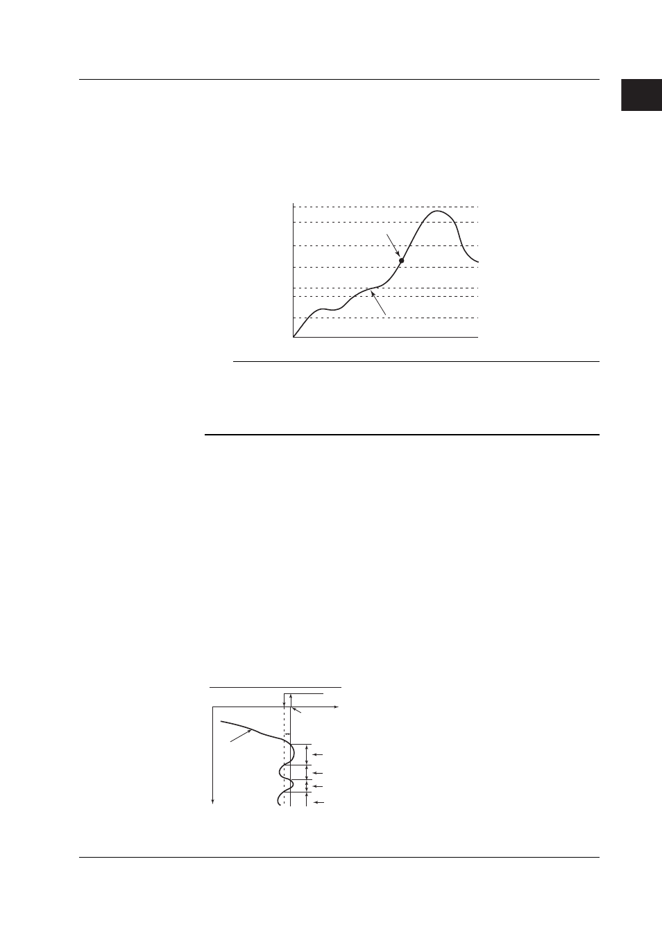
• Zone PID method
The measurement span is divided into a maximum of seven zones using reference
points. The optimum PID constant is preassigned to each zone, and the PID constant
(in actuality, other control parameters that are registered using the PID number are
included) is automatically switched according to the PV. This method is suited for
controlling equipment such as reactors in which the chemical reaction gain varies
depending on the temperature.
No.1 PID
Maximum value of
measurement span
Reference point 1
Reference point 2
Reference point 3
Reference point 4
Reference point 5
Reference point 6
No.2 PID
No.3 PID
No.4 PID
No.5 PID
No.6 PID
No.7 PID
Minimum value of
measurement span
Change in the
PV.
If the current PV is here, PID
constant of PID No. 5 is used
for control.
Note
•
When performing program control operation on models with the program control option,
you will select between segment PID method (zone PID selection OFF) and zone PID
method.
•
For a description on auto tuning, which automatically sets the optimum PID constant, see
section 1.12, “Tuning.”
Alarm Output
When the control action status matches the preset status (up to 4 points per loop), the
CX2000 can output a relay contact signal from the control output terminal block/DIO
expansion terminal block, and output it to the internal switches. Also you can display the
alarm occurrence status on the screen. In relay contact output or output to the internal
switches, you can select and assign the type of alarm you wish to output at each output
terminal of the control output terminal block, the control DIO extension terminal block, or
internal switches.
Alarm Type
You can select the alarm type from below. For a detailed explanation on each alarm
output, see section 1.10, “Control Alarm Related Settings.”
PV high-limit alarm, PV low-limit alarm, deviation high-limit alarm, deviation low-limit
alarm, deviation high & low limit alarm, deviation within high & low limits alarm, SP high-
limit alarm, SP low-limit alarm, output high-limit alarm, and output low-limit alarm.
Alarm Hysteresis
You can set a hysteresis to the setpoints used in the activation and releasing of the alarm.
ON
OFF
Hysteresis
PV
Alarm ON
OFF
ON
OFF
Example of PV high limit alarm
Alarm setpoint
Time
1.2 Control Function Overview