Contact input (digital in/remote) wiring – Yokogawa Data Acquisition with PID Control CX2000 User Manual
Page 136
2-19
IM 04L31A01-01E
Installation and Wiring
3
2
1
4
5
6
7
8
9
10
11
12
13
14
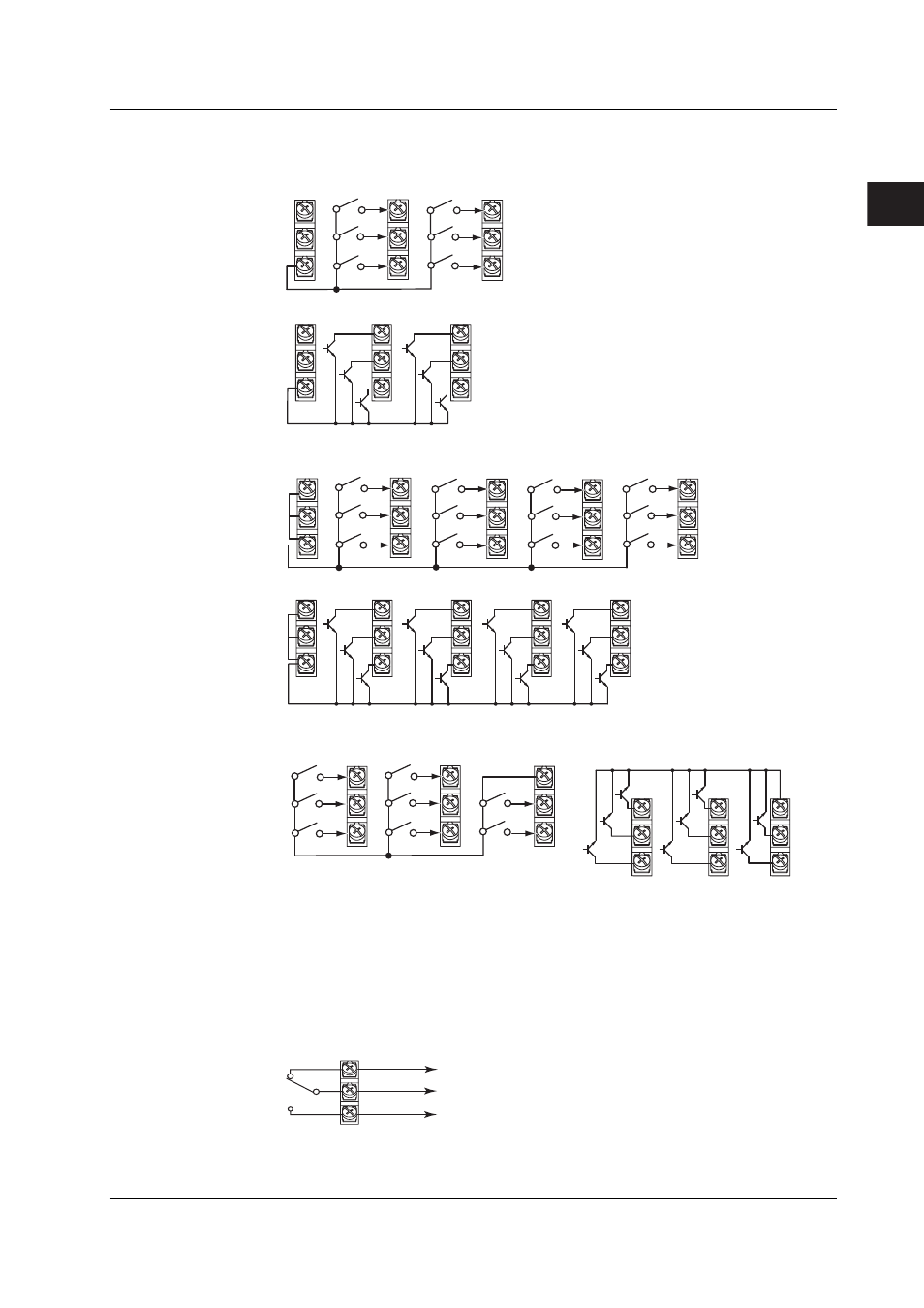
Contact Input (DIGITAL IN/REMOTE) Wiring
• Relay contact input
2
1
4
6
3
5
C
1
2
3
4
5
6
C
• Transistor input
Control output terminal block (DIGITAL IN)
• Relay contact input
C
C
C
• Transistor input
7
8
9
10
11
12
1
2
3
4
5
6
C
C
C
Control expansion DIO terminal block (DIGITAL IN)
7
8
9
10
11
12
1
2
3
4
5
6
Measurement remote input (REMOTE) of the measurement alarm option terminal block
(/A6R, /A4FR)
C
1
2
3
4
5
6
7
8
• Transistor input
• Relay contact input
C
1
2
3
4
5
6
7
8
Relay Contact Input and Transistor Input Specifications
Input signal:
Non-voltage contact, open collector
Input conditions:
0.5 V or less (30 mADC) when turned ON, leakage current of 0.25
mA or less when turned OFF
Input format:
Photocoupler isolation (shared common)
Withstand voltage: 500 VDC for 1 minute (between the input terminal and earth)
Contact Output (ALARM, FAIL, MEMORY of the Measurement Alarm Option Terminal
Blocks) Wiring
C
NO
NC
250 VAC/3A,
250 VDC/0.1 A(resistive load)
Relay Output Specifications
Output format:
Relay contact
Contact rating:
250 VAC (50/60 Hz)/3 A or 250 VDC/0.1 A (resistive load)
2.3 Wiring