Yokogawa Data Acquisition with PID Control CX2000 User Manual
Page 413
App-44
IM 04L31A01-01E
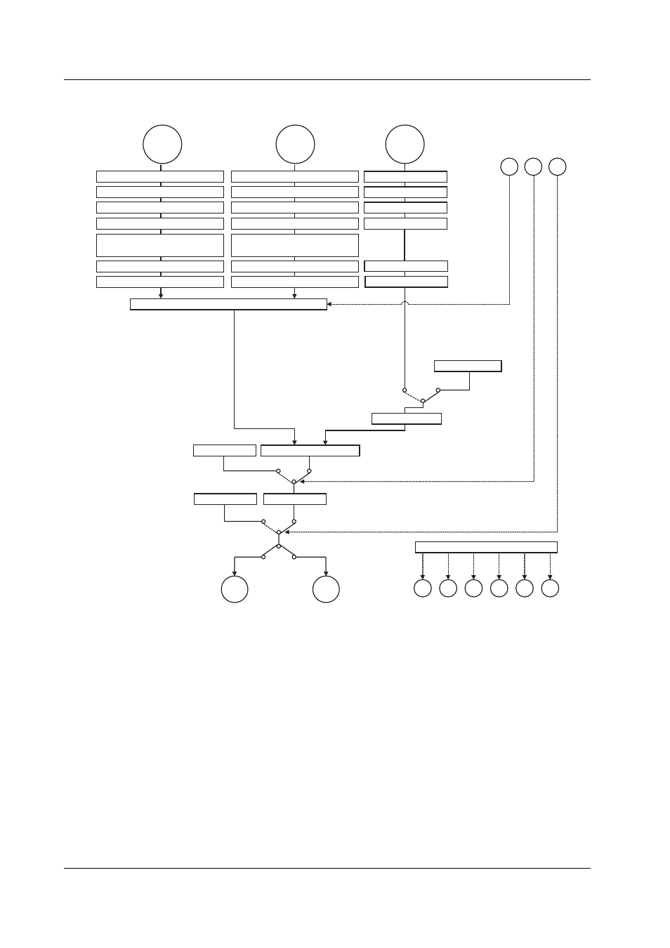
Loop Control with PV Switching (Fixed-Point Control)
PV
input
1
Contact input
Loop control with PV switching
PV switching
PV
input
2
Control computation section 2
Manual operation
Preset output
Current or
pulse
Relay
Run
Auto
Manual
Stop
Stop/Run switching
Manual/Auto switching
Output limiter
DI
DI
DI
Control output
Remote
input
Input type selection
Unit selection
Analog input range conversion
Square root computation
SP ramp-rate setting
SP 1 to 8
Local
Remote
Input type selection
Unit selection
Analog input range conversion
Square root computation
Ten-segment linearizer approximation/
ten-segment linearizer bias
PV input bias
PV input filter
Input type selection
Unit selection
Analog input range conversion
Square root computation
Ten-segment linearizer approximation/
ten-segment linearizer bias
PV input bias
PV input filter
DO
DO
DO
DO
DO
DO
Alarm1 Alarm2 Alarm3 Alarm4 Alarm1 Alarm2
Alarm function
Note: There are 6 contact input terminals and
6 contact output terminals on a single
control output terminal block.
The functions that can be assigned to
each input/output terminal vary depending
on the control mode and whether program
operation is enabled.
Remote input filter
Ratio bias computation
Appendix 7 Control Functon Blodk Diagram