Yokogawa Data Acquisition with PID Control CX2000 User Manual
Page 73
1-61
IM 04L31A01-01E
Explanation of Functions
3
2
1
4
5
6
7
8
9
10
11
12
13
14
Note
•
For current inputs, a shunt resistor is attached to the input terminal to convert the signal to
voltage input. The following table shows the available shunt resistors. For example, a
250-Ω shunt resistor is used to convert the signal to 1 to 5 V for 4-20 mA input.
Name
Model
Resistance
Shunt resistor
4159 20
250 Ω ± 0.1%
(for screw terminals)
4159 21
100 Ω ± 0.1%
4159 22
10 Ω ± 0.1%
•
The square-root computation method of the CX2000 is indicated below.
F = (F - F )
x
max
min
V - V
x
min
max
min
V - V
=
min
F
Meanings of the symbols are shown below.
V
min
: span lower limit, V
max
: span upper limit, F
min
: scale lower limit after conversion,
F
max
: scale upper limit after conversion, V
x
: input voltage, F
x
: scaling value.
If the value inside the root is negative, the computed result is displayed as follows.
When F
min
< F
max
: “–*****”
When F
min
> F
max
: “+*****”
Input Range and Measurable Range
When the input type is set to DC voltage, thermocouple, resistance temperature detector,
or ON/OFF input, you will select the range to match the input signal. For DC voltage, select
the measurable range (select [20mV] for “–20.00 to 20.00 mV”). For thermocouple or
resistance temperature detector, select the type. For example, the type selections for the
thermocouple are [R], [S], [B], [K], [E], [J], [T], [N], [W], [L], [U], [PLATINEL], [PR40-20], and
[W3Re/W25Re]. If [R] is selected, the measurable range is 0.0 °C to 176.0 °C. In addition,
you will set the measurement span ([Span lower limit] and [Span high limit]) within the
measurable range as the actual range for making measurements.
Burnout Detection
When measuring the temperature using a thermocouple, you can have the measurement result
set to positive overrange
*1
or negative overrange
*2
when a burnout occurs. Burnout can be set
on each measurement channel. The initial setting is set so that burnout is not detected.
*1 Positive overrange refers to the condition in which the input signal is exceeding the upper limit of
the measurable range of the input range. The measured value is show as “+*****”.
*2 Negative overrange refers to the condition in which the input signal is less than the lower limit of
the measurable range of the input range. The measured value is show as “–*****”.
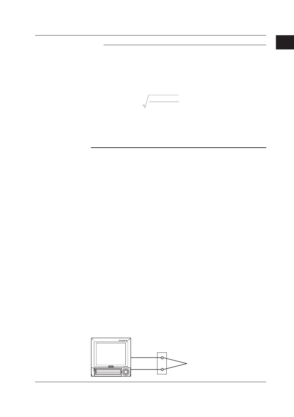
Reference Junction Compensation
When measuring the temperature using a thermocouple, the reference junction compensation
can be used. You can select whether to use the reference junction compensation provided by
the CX2000 or an external reference junction compensation. If you are using an external
reference junction compensation, you will also set the reference voltage. The initial setting is set
so that the reference junction compensation provided by the CX2000 is used. When using the
external reference junction compensation, set an appropriate reference junction
compensation voltage. As in the example in the following figure, if the reference junction
temperature for the external reference junction compensation is T
0
°C, set the
thermoelectromotive force of the 0-°C reference for T
0
°C as the reference junction
compensation voltage.
CX2000
External reference junction compensation
(Hold the contact point of the thermocouple
and copper wire at T0 °C)
Thermocouple
Copper wire
1
2
3
4
DISP/
ENTER
1.14 Measurement Function > Measurement Input Related Settings