2 control function, Control function -3, General control functions – Yokogawa Data Acquisition with PID Control CX2000 User Manual
Page 351
14-3
IM 04L31A01-01E
Specifications
14
14.2 Control Function
General Control Functions
Control Mode
Select from three controls for every two loops: single loop control, cascade control, and loop
control with PV switching (however, only single loop control is possible on loops 5 and 6).
Control Computation Function
Continuous PID control, on/off control, time proportional PID control
PID control:
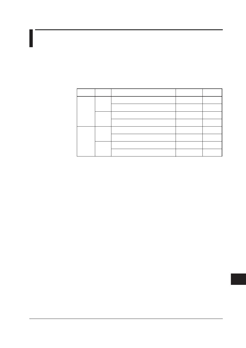
PID Control
Method
PV derivative
type PID
Deviation
derivativ type PID
PV derivative
type PID
Deviation
derivative type PID
PV derivative
type PID
PV derivative
type PID
PV derivative
type PID
PV derivative
type PID
Local and not the secondary side of a cascade
connection
Remote or secondary side of a cascade
connection
Local and not the secondary side of a cascade
connection or hold or soak
During program control (excluding hold and soak)
or the secondary side of a cascade connection
Local and not the secondary side of a cascade
connection
Remote or secondary side of a cascade
connection
Local and not the secondary side of a cascade
connection or hold or soak
During program control (excluding hold and soak)
or the secondary side of a cascade connection
PID control
mode
Standard
PID
control mode
Fixed-point
control mode
Operation
mode
Fixed-point
control
operation
Program
control
operation
Fixed-point
control
operation
Program
control
operation
Control
Output Bump
Yes
Yes
Yes
Yes
No
Yes
No
Yes
*
The secondary side of a cascade connection refers to the secondary loop of which the cascade control
mode is set to Cascade (of the Auto, Manual, and Cascade selections).
Operation Status
PID parameters:
8 sets/loop
Zone PID switch point:
Up to 6
Super function (overshooting suppression): Available
Tracking function:
SP tracking
PV tracking
Anti-reset windup (over-integration prevention)
Control period:
250, 500, 1000 ms
Operation Mode Switching
Remote, local, and program switching
Manual, auto, and cascade switching
Run/stop switching
Stop: Outputs the preset output
Auto tuning enable/disable switching
Principle: Limit cycle method
Selectable Range of Control Parameters
Proportional band:
0.1 to 999.9%
Integral time:
0 to 6,000 s
Derivative time:
0 to 6,000 s
On/Off control hysteresis width:
0.0 to 100.0% of the measurement span
Preset output:
–5.0 to 105.0% of the control output (output when control
computation is stopped, when PV input is burned out, and
when measurement input is erroneous)
Selectable range of high/low limit of the output limiter:
–5.0 to 105.0% of measurement span
Shutdown function:
Output up to 0 mA of control output during manual operation at
4 to 20 mA output (shutdown at less than or equal to –5.1%)
Output Velocity Limiter:
Off or 0.1 to 100.0%/s