17 data storage function, Data storage function -89 – Yokogawa Data Acquisition with PID Control CX2000 User Manual
Page 101
1-89
IM 04L31A01-01E
Explanation of Functions
3
2
1
4
5
6
7
8
9
10
11
12
13
14
1.17 Data Storage Function
Data Acquisition to the Internal Memory
Control Data
The following control related data can be acquired to the internal memory. Control
related data includes the PV, SP, and OUT of external loops created through Green
series communications in addition to those of internal loops.
Data Type
Data Content
Display data
Maximum/minimum values of PVs, SPs, and control outputs (OUT) for every interval of acquisition to
the internal memory.
Event data
Instantaneous value of PV at every specified sampling interval.
Manual sampled data
Data in ASCII format containing the time and PV at the time of key operation or remote input.
Alarm summary data
Channel on which alarm is occurred, alarm type, and time of occurrence and release.
Event summary data
Loop number at which the time event or PV event occurred and the time of occurrence and release.
Operation mode
Information of operation mode switching.
summary data
Internal control channel (internal loop channel) assignments
The data of 6 loops is assigned to channel numbers as follows.
Loop 1 PV: 101, Loop 1 SP: 102, Loop 1 OUT: 103
•••
Loop 6 PV: 116, Loop 6 SP: 117, Loop 6 OUT: 118
External control channel (external loop channel) assignments
The data of 16 loops is assigned to channel numbers as follows.
External loop 1 PV: 201, External loop 1 SP: 202, External loop 1 OUT: 203
•••
External loop 16 PV: 246, External loop 16 SP: 247, External loop 16 OUT: 248
Measurement Data
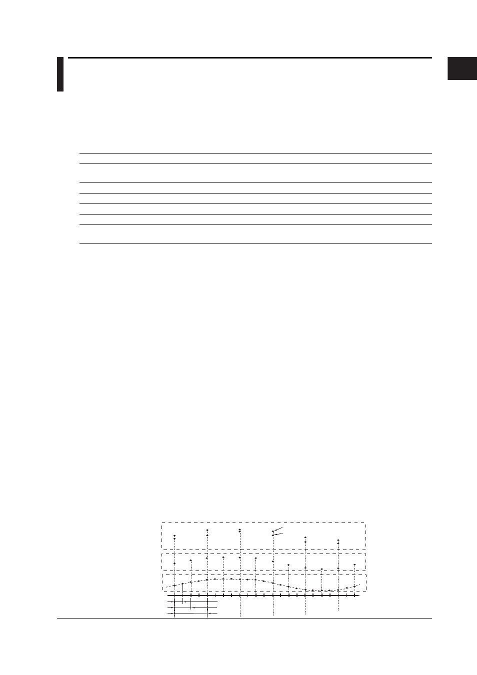
• Display data and event data
The measured/computed/control data can be written to two types of data, display data
and event data, in the internal memory of the CX2000.
Display data
Data used to display waveforms on the CX2000 display. Display data consists of maximum
and minimum values of the measured or computed data sampled at the scan interval within
the time period corresponding to one dot on the time axis on the display. The display data
that is saved can be likened to the conventional recording on the chart sheet and is useful for
observations of long-term changes. The data is saved in binary format.
Event data
Event data consists of instantaneous values of the measured/computed/control data
at specified sampling intervals. This is useful when you wish to observe the
measured/computed/control data more in detail than display data. If the sampling
interval is set to the same value as the scan interval, all the measured or computed
data sampled at the scan interval can be acquired to the internal memory. The data is
saved in binary format.
Measured/computed/
control data per scan
interval
Display data
Event data
Sampling interval of dislay data (time equivalent to 1 dot on the display)
Scan interval
Time
Sampling interval of event data
Max. value per sampling interval
Min. value per sampling interval