Quantum Data 881 User Manual
Page 519
881/882 Video Test Generator User Guide (Rev A.22)
501
2. For the TPA-ACA-3R, connect the cables as follows:
a. Connect an HDMI-to-HDMI cable between the HDMI connector on the source
device under test and the first HDMI connector on the TPA-ACA-3R Test Point
Adapter labeled DUT1.
b. Connect an HDMI-to-HDMI cable between the HDMI connector on the sink device
under test and the second HDMI connector on the TPA-ACA-3R Test Point Adapter
labeled DUT2.
c. Connect an HDMI-to-HDMI cable between the HDMI OUT connector on the 882
generator/analyzer and the third HDMI connector on the TPA-ACA-3R Test Point
Adapter labeled OUT1.
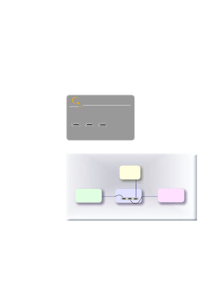
The figure below shows the TPA-ACA-3R device.
The following diagram illustrates the test setup.
ACA Passive Monitor
Model TPA-ACA-3R
DUT1
DUT2
OUT1
Device Under Test - DUT1
Source
Device Under Test - DUT2
Sink (Display)
ACA Passive Monitor
DUT1
DUT2
OUT1
HDMI TX
HDMI RX
HDMI TX
882CA
TPA-ACA-3R