Subroutine call timing -20 – Freescale Semiconductor StarCore SC140 User Manual
Page 200
5-20
SC140 DSP Core Reference Manual
Instruction Timing
change-of-flow occurs to a new execution set spread over two fetch sets, two new fetches must be
read from memory.
•
The subroutine call instructions (JSR, JSRD, BSR, and BSRD) need one free cycle in order to
push the return PC and SR onto the stack. Normally, a subroutine call instruction uses one of the
idle cycles while the pipeline is filling up so that no stall occurs. However, one stall cycle is added
if the instructions that execute in parallel with the subroutine CALL need more cycles than a
specific number. In essence, an additional cycle is added to a subroutine call instruction when
(C
jn
+ C
d
)
≥ C
j
where:
— C
jn
Highest cycle count of instructions grouped with CALL
— C
j
Cycle count of the non-delayed version of CALL (for example, BSR and BSRD, C
j
= 4)
— C
d
Cycle count of the set in the delayed slot (if CALL is not a delayed instruction, C
d
= 0)
Example 5-7 shows a case when a stall cycle is added.
Example 5-7. Subroutine Call Timing
JSRD _subr
MOVE.W (R0+2),D0
; C
j
= 3, C
jn
= 2
ADDA R0,R1
; C
d
= 1
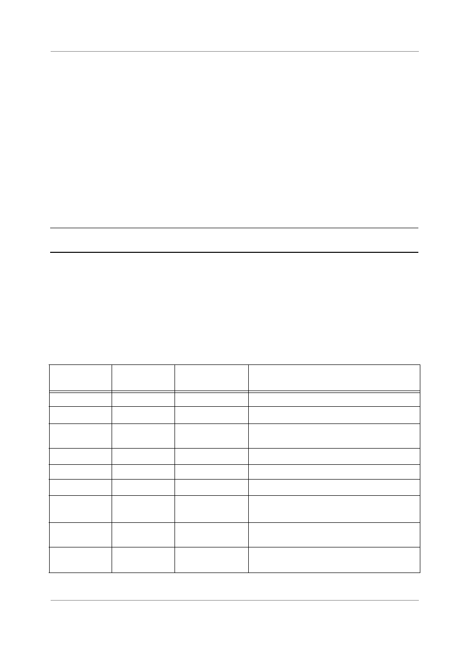
Table 5-8 summarizes the cycle count for change-of-flow instructions. In the Number of Cycles column,
C
d
represents the length of the delay slot in cycles. The technique of subtracting the cycles of the delay slot
instructions from the cycle count of the delayed change-of-flow instruction assumes that the delay slot
instructions’ cycles are counted separately. The net count should be zero since the instructions are
“hidden” in the delay slot. The minimum number of cycles is specified for the delayed instructions, but
only when the number of cycles is small enough for the minimum number of cycles to actually occur. If no
number appears in the Minimum Number of Cycles column, the equation in the Number of Cycles column
applies, with no minimum.
Table 5-8. Number of Cycles Needed by Change-of-Flow Instructions
Instruction
Number of
Cycles
Minimum Number
of Cycles
Condition
JMP
3
JMPD
3 – C
d
1
JSR
3
4
C
jn
< 3
C
jn
≥ 3
JSRD
1+ C
jn
BRA, BSR
4
BRAD
4 – C
d
1
BSRD
4 – C
d
1+ C
jn
2
C
jn
+C
d
< 4
C
jn
+C
d
≥ 4
Jc/Bc
4
1
Jump is taken.
Jump is not taken.
JcD/BcD
4 – C
d
1
Jump is taken.
Jump is not taken.