2 jtag scan paths, Jtag scan paths -3, Jtag and eonce multi-core interconnection -3 – Freescale Semiconductor StarCore SC140 User Manual
Page 113: Jtag instructions -3, Jtag tap controller
Overview of the Combined JTAG and EOnCE Interface
SC140 DSP Core Reference Manual
4-3
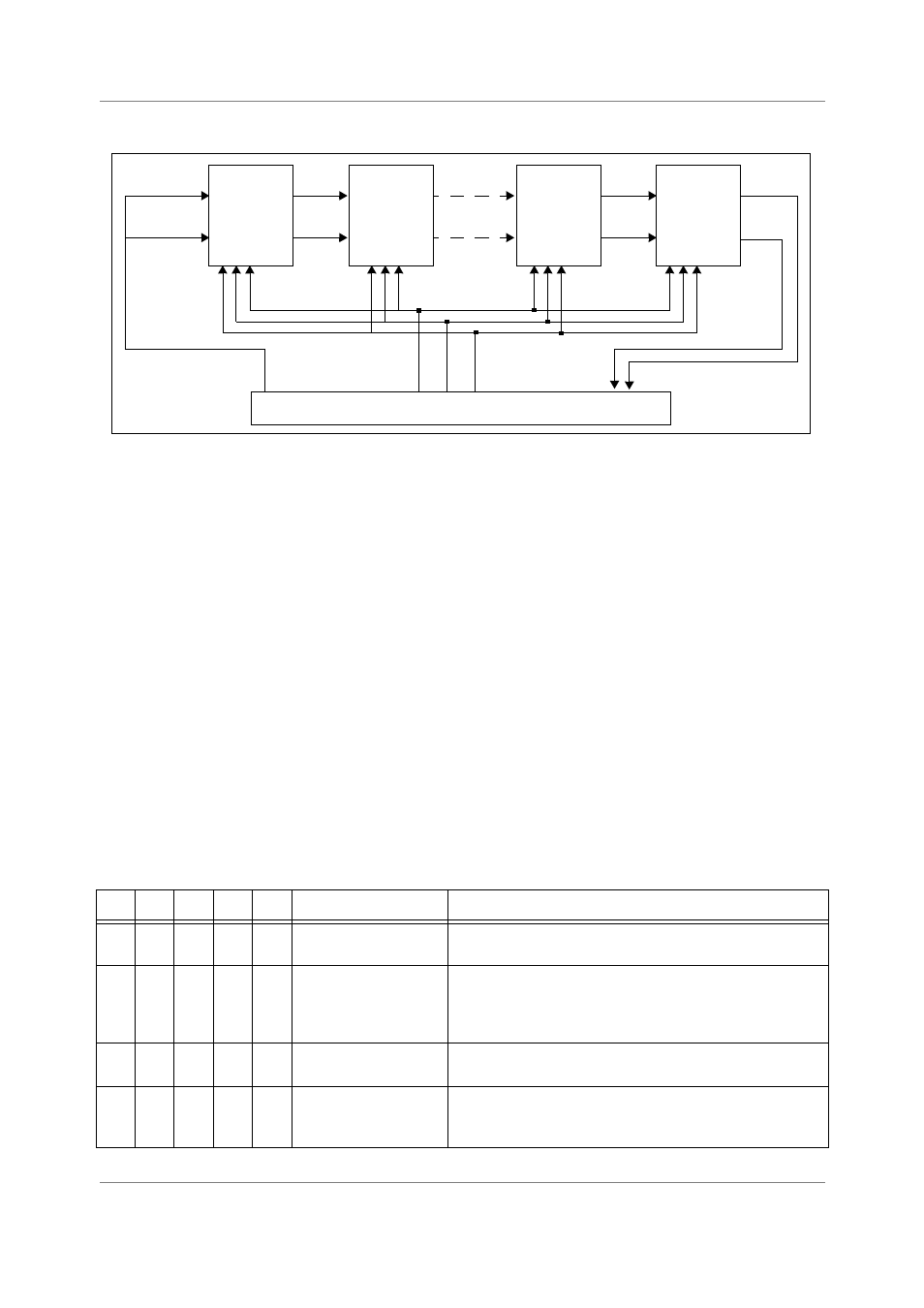
Figure 4-1. JTAG and EOnCE Multi-core Interconnection
To access the EOnCE module of each of the cores through the JTAG port, it is important to know the
following:
•
The JTAG scan paths
•
The JTAG instructions
•
The EOnCE control register value
4.2.2 JTAG Scan Paths
The host controller communicates with SoC via the Test Access Port (TAP) controller using the following
scan paths:
•
Select-IR JTAG scan path. Used when the host sends the JTAG instructions shown in Table 4-2 to
the SoC.
•
Select-DR JTAG scan path. used for data transfer between the HOST and the SoC, which
corresponds to the current JTAG instruction exist in the Jtag IR register.
Table 4-2. JTAG Instructions
B4
B3
B2
B1
B0
Instruction
Description
0
0
0
0
0
EXTEST
Selects the Boundary Scan Register. Forces a predictable internal
state while performing external boundary scan operations.
0
0
0
0
1
SAMPLE/PRELOAD
Selects the Boundary Scan Register. Provides a snapshot of
system data and control signals on the rising edge of TCK in the
Capture-DR controller state. Initializes the BSR output cells prior
to selection of EXTEST or CLAMP.
0
0
0
1
0
IDCODE
Selects the ID Register. Allows the manufacturer, part number
and version of a component to be identified.
0
0
0
1
1
CLAMP
Selects the Bypass Register. Allows signals driven from the
component pins to be determined from the Boundary Scan
Register.
choose_tdi
tdi
tdo
tck
eonce_reset
choose_clock_dr
tdi
JTAG TAP Controller
EOnCE1
EOnCE2
EOnCEn-1
EOnCEn