Eonce controller block diagram -17, Eonce controller register set -17 – Freescale Semiconductor StarCore SC140 User Manual
Page 127
EOnCE Module Internal Architecture
SC140 DSP Core Reference Manual
4-17
•
Reading and writing EOnCE registers from the software
•
Real-time JTAG port access
•
Real-time data transfer
•
Executing instructions while in debug state
•
Samples core PC information in various states
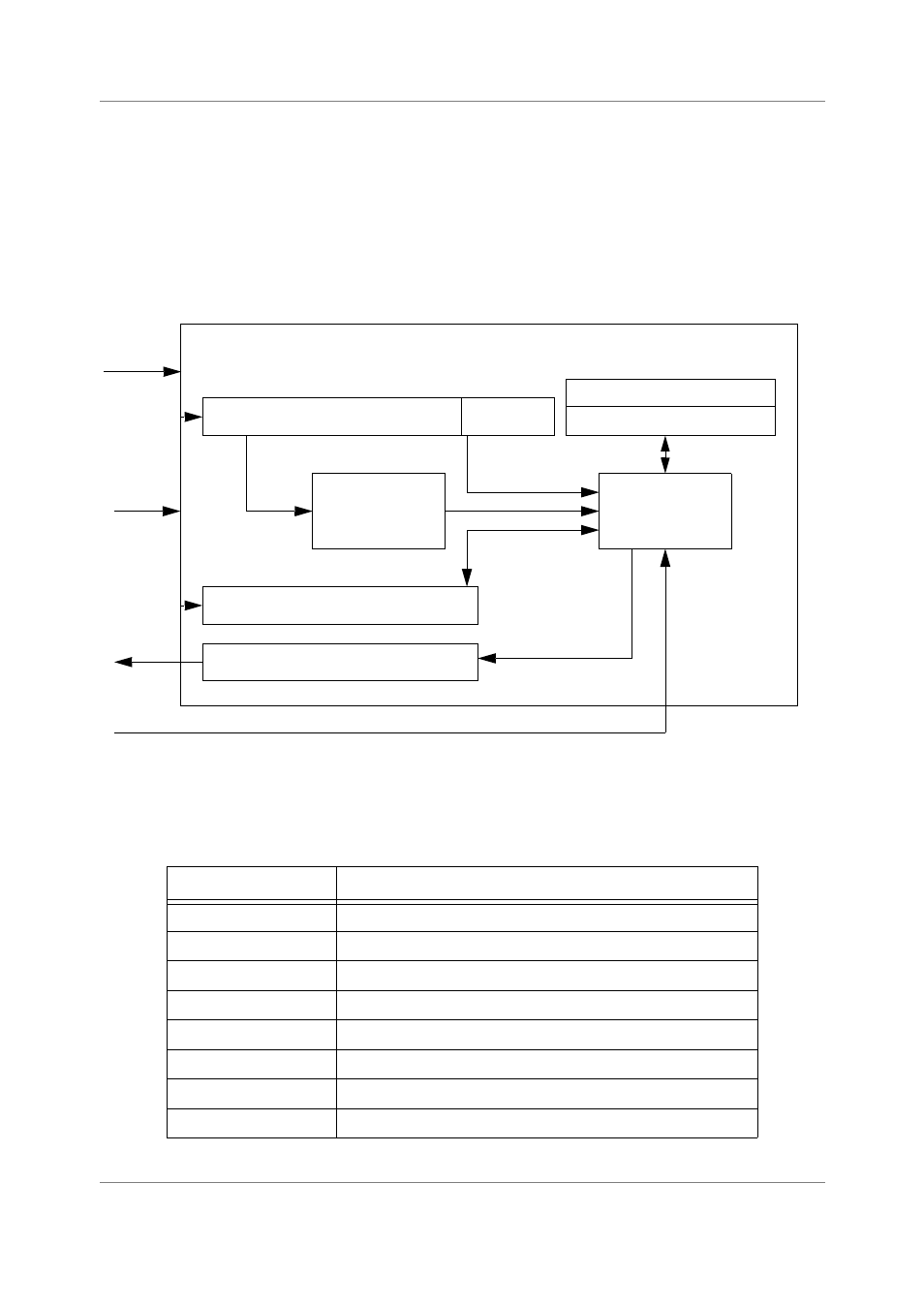
Figure 4-8 displays the EOnCE controller block diagram.
Figure 4-8. EOnCE Controller Block Diagram
The EOnCE controller register set is shown in Table 4-6.
Table 4-6. EOnCE Controller Register Set
Register Name
Description
ECR
EOnCE command register
ESR
EOnCE status register
EMCR
EOnCE monitor and control register
ERCV
EOnCE receive register
ETRSMT
EOnCE transmit register
EE_CTRL
EE signals control register
CORE_CMD
EOnCE core command register
PC_EXCP
PC of the execution set causing illegal or overflow exception
TCK
TDI
TDO
Command Register
Control
Logic
Status Register
Monitor and Control Register
Address
6
0
Address
Decoder
Receive Register
Transmit Register
Update Signal from the TAP Controller