3 main capabilities of the eonce module, 1 eonce signals, Main capabilities of the eonce module -10 – Freescale Semiconductor StarCore SC140 User Manual
Page 120: Eonce signals -10, Typical debugging system -10
4-10
SC140 DSP Core Reference Manual
Main Capabilities of the EOnCE Module
4.3 Main Capabilities of the EOnCE Module
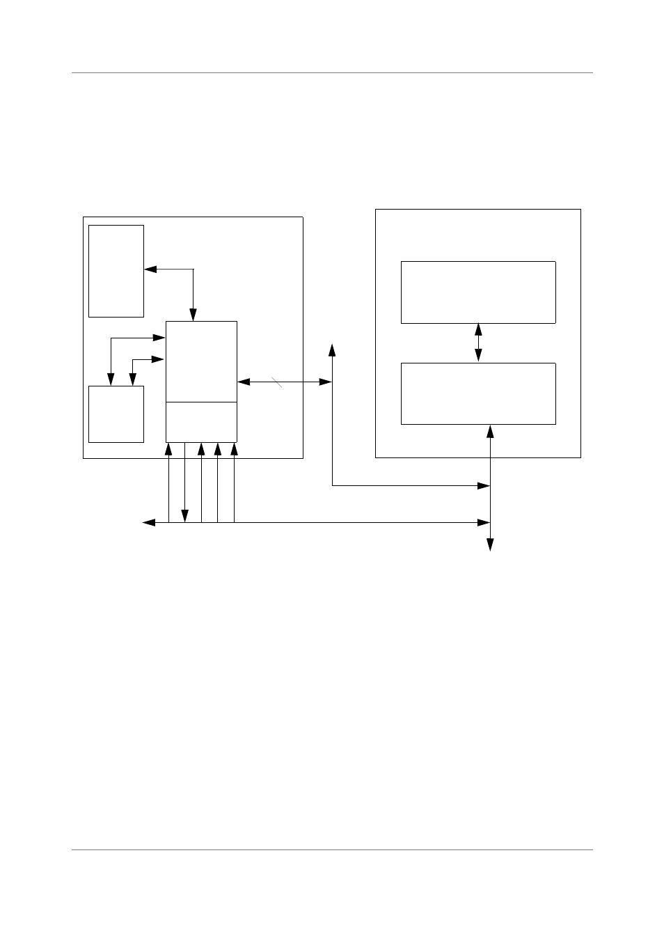
While the JTAG port provides board test capability, the EOnCE module provides emulation and debug
capability. The EOnCE module permits full-speed, real-time, and non-intrusive emulation for a target
system or a SC140 development board. This section describes the environment in which the EOnCE
module is used for debugging a real-time embedded application. Figure 4-6 shows a typical debug
environment where the core resides in a target DSP system.
Figure 4-6. Typical Debugging System
4.3.1 EOnCE Signals
The JTAG signals TCK, TDI, and TDO are used to shift data and instructions in and out (see Table 4-1 on
page 4-2 for a description of the JTAG signals). For emulation of specific functions, six dedicated EOnCE
event signals (EE0–EE5) are available as well as one data event (EED) signal and two event counter (EC)
signals.
The two event counter signals EC0 and EC1 allow the event counter to count off-core events such as cache
hits/misses, memory contention, external wait-states, etc. These inputs are assumed synchronous to the
core clock and support a counting rate up to the core frequency. EC0 and EC1 use is derivative-dependent.
The EE signals can be connected to any on-chip peripheral block such as DMA or TIMER as well as
off-chip. This enables an external device to intervene asynchronously in the SC140 debugging process, or
to serve as an indication of the events occurring inside the DSP device. Some of these signals have
multiple functions programmed by the EE Signals Control Register (EE_CTRL). See
for further information.
Memory
Host
Computer
Debugging
Software
Debugging
Hardware
Target DSP
Control
SC140
Core
Data
JTAG
Interface
EOnCE
EOnCE Signals
JTAG Signals
EE
TRST
TMS
TCK
TDO
TDI
7