Status register -sr -2, Status register description -2, Table 3-1 describes the various sr bits – Freescale Semiconductor StarCore SC140 User Manual
Page 102
3-2
SC140 DSP Core Reference Manual
Core Control Registers
•
ILLEGAL
•
DEBUG, DEBUGEV (if configured in the EOnCE to generate an exception)
The following instructions implicitly pop the
SR
from the stack:
•
RTE/D
Appendix A, “SC140 DSP Core Instruction Set,”
for a full description of these instructions.
The pipeline imposes certain programming rules relating to the minimum distance between writing the SR
and when the change takes effect. For further details, refer to
Chapter 7, “Programming Rules.”
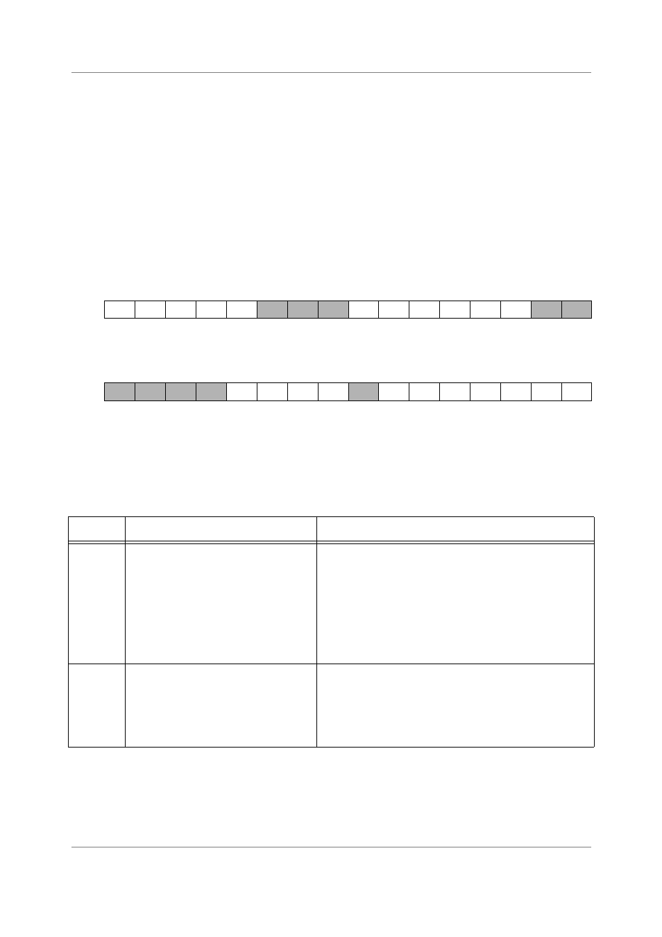
Figure 3-1 shows the bits that make up the status register
.
Figure 3-1. Status Register -SR
Table 3-1 describes the various SR bits.
BIT 31
30
29
28
27
26
25
24
23
22
21
20
19
18
17
16
SLF
LF3
LF2
LF1
LF0
I2
I1
I0
OVE
DI
EXP
TYPE
rw
rw
rw
rw
rw
rw
rw
rw
rw
rw
rw
rw
rw
rw
rw
rw
RESET
0
0
0
0
0
0
0
0
1
1
1
0
0
1
0
0
BIT 15
14
13
12
11
10
9
8
7
6
5
4
3
2
1
BIT 0
VF3
VF2
VF1
VF0
S
S1
S0
RM
SM
T
C
TYPE
rw
rw
rw
rw
rw
rw
rw
rw
rw
rw
rw
rw
rw
rw
rw
rw
RESET
0
0
0
0
0
0
0
0
0
0
0
0
0
0
0
0
Table 3-1. Status Register Description
Name
Description
Settings
SLF
Bit 31
Short Loop Flag — Indicates (when set)
that the active loop is a short loop, which
means that it contains only one or two
execution sets.
At the start of an interrupt service routine
(ISR), the SR (including the SLF bit) is
pushed onto the software stack and the
SLF bit is cleared.
This bit is cleared at core reset.
0 = Active loop length is three or more execution sets
1 = Active loop length is one or two execution sets
LF3
Bit 30
Loop Flag 3 — Indicates (when set) that
hardware loop #4 is enabled. At the start
of an ISR, the SR (including the LF3 bit)
is pushed onto the software stack and
the LF3 bit is cleared.
This bit is cleared at core reset.
0 = Hardware loop #4 not enabled
1 = Hardware loop #4 enabled