Multiple lines – Grass Valley NV9000-SE v.5.0 User Manual
Page 440
422
Tielines
Tieline Configuration Page
(A selected line is green-and-black striped. Sometimes it is thin and sometimes it is thick,
because of artifacts in the rendering engine.)
Ports already consumed by tielines are not displayed.
Ports used by NV9000 devices should not be used for tielines, but there is no representation
of those ports in the ‘Graph’ section.
It is not sufficient just to draw the line. To each line, you must assign a set of signal types.
You can do this, when a line is selected, by checking the check boxes of the signal types in the
upstream and downstream ‘Signal Types’ sections of the page. You can also check the ‘Virtual
Level’ check boxes to enable all the signal types associated with the upstream virtual level and
with the downstream virtual level.
When you have finished drawing lines between ports and assigning signal types to the lines, do
not forget to click ‘Save’ at the bottom of the page. Otherwise
Multiple Lines
In many cases, you can draw multiple lines in the ‘Graph’ section.
Keep in mind that the tieline configuration page represents exactly one simple tieline. The several
lines that you draw belong to one simple tieline and represent connections of different signal
types.
Exactly what the cabling for the tieline is and what signal conversion devices you might have in
the tieline are not represented in the graph.
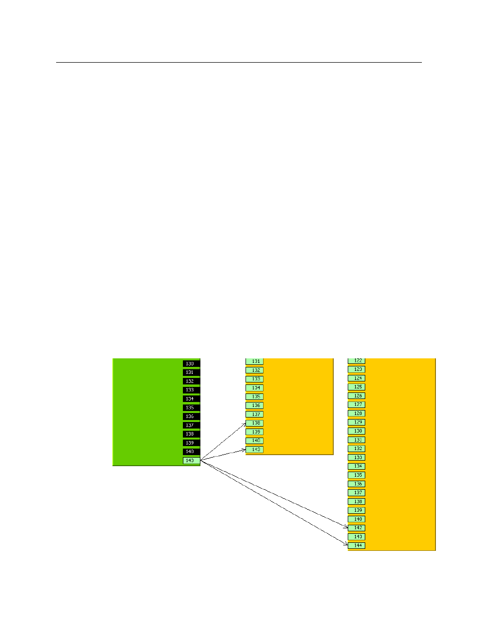
Fanout (1:N) and fanin (N:1) are permissible, but N:N — arcs from multiple upstream ports to
multiple downstream ports — is not permissible.
The multiple arcs describe a single simple tieline. When the tieline is used for a route, all its arcs
are live and conduct signals. And when the tieline is released, all its arcs are released.
Here is an example of “fanout”: