Multi-destination configuration, Single-destination configuration, Nv9606 – Grass Valley NV9000-SE v.5.0 User Manual
Page 259: Nv9606 panel description
241
NV9000-SE Utilities
User’s Guide
Multi-Destination Configuration
A panel configured in multi-destination mode has buttons that represent 2 sources and a desti-
nation. Pressing a button selects one of the sources and the destination and performs an
immediate take
—
to the destination assigned to the button. (A “shift” button switches between
the two sources of the source buttons.)
A typical multi-destination configuration might, for example, provides 8 destinations with up to
8 sources available for each one, with the 4 buttons on the right assigned to other functions:
Single-Destination Configuration
It is possible to configure the panel for single-destination operation, in either limited X-Y mode
or multi-destination mode.
NV9606
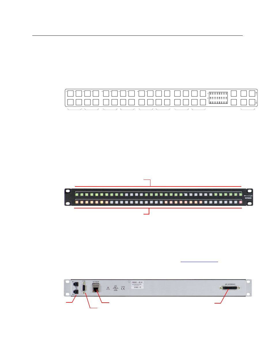
NV9606 Panel Description
The NV9606 is a 1RU control panel. It has 68 backlit function buttons:
The NV9606 can operate either by itself as a stand-alone panel or as a extension of an NV9607
control panel.
An equivalent virtual panel
—
the NV9606V
—
is available.
When the panel is stand-alone, the function buttons are limited: an operator can select sources
and destinations or execute salvos. When the panel is used as an NV9607 extension, the set of
functions is approximately that of the NV9607. As an extension to an NV9607, it can operate in
any of the 4 modes configured for that particular NV9607. See
, following.
The sets of functions differ in the different operating modes.
At the rear of the panel are power, serial control, Ethernet, and GPIO connectors:
You connect the NV9606 to the NV9000 system using the Ethernet connector.
Dest A
Dest B
Dest C
Dest D
Dest E
Dest F
Dest G
Dest H
Misc.
Function Buttons
Function Buttons
Ethernet (RJ-45)
GPIO (DB25)
Power
Serial (RS-422)