Single-destination “mode, Multi-destination configuration – Grass Valley NV9000-SE v.5.0 User Manual
Page 350
332
Control Panels
NV9649
Single-Destination “Mode”
The panel, when it is in server mode, is
—
by definition
—
a single-destination panel. (The desti-
nation is defined as a panel option at configuration.)
This does not contradict the idea that the server can assign destinations to its associated
NV9648 clients.
The panel, in either LCD XY/MD or NV9609 mode, can be configured as a single-destination
panel by defining a default destination during configuration and providing no destination
selection buttons.
Multi-Destination Configuration
Multi-destination (MD) devices are a subset of all destination devices. You can configure a panel
to have from 8 to 512 MD destinations in increments of 8 destinations. Not all of those need be
used. The limit to the number of MD devices is a panel option.
Follow these guidelines to configure MD devices.
1 Click any button in the panel image. In the button definition section, choose ‘Selection’ from
the drop-down list. A ‘Display Index’ field and an ‘Edit Multi-Dest Devices’ button appear in
the button definition section.
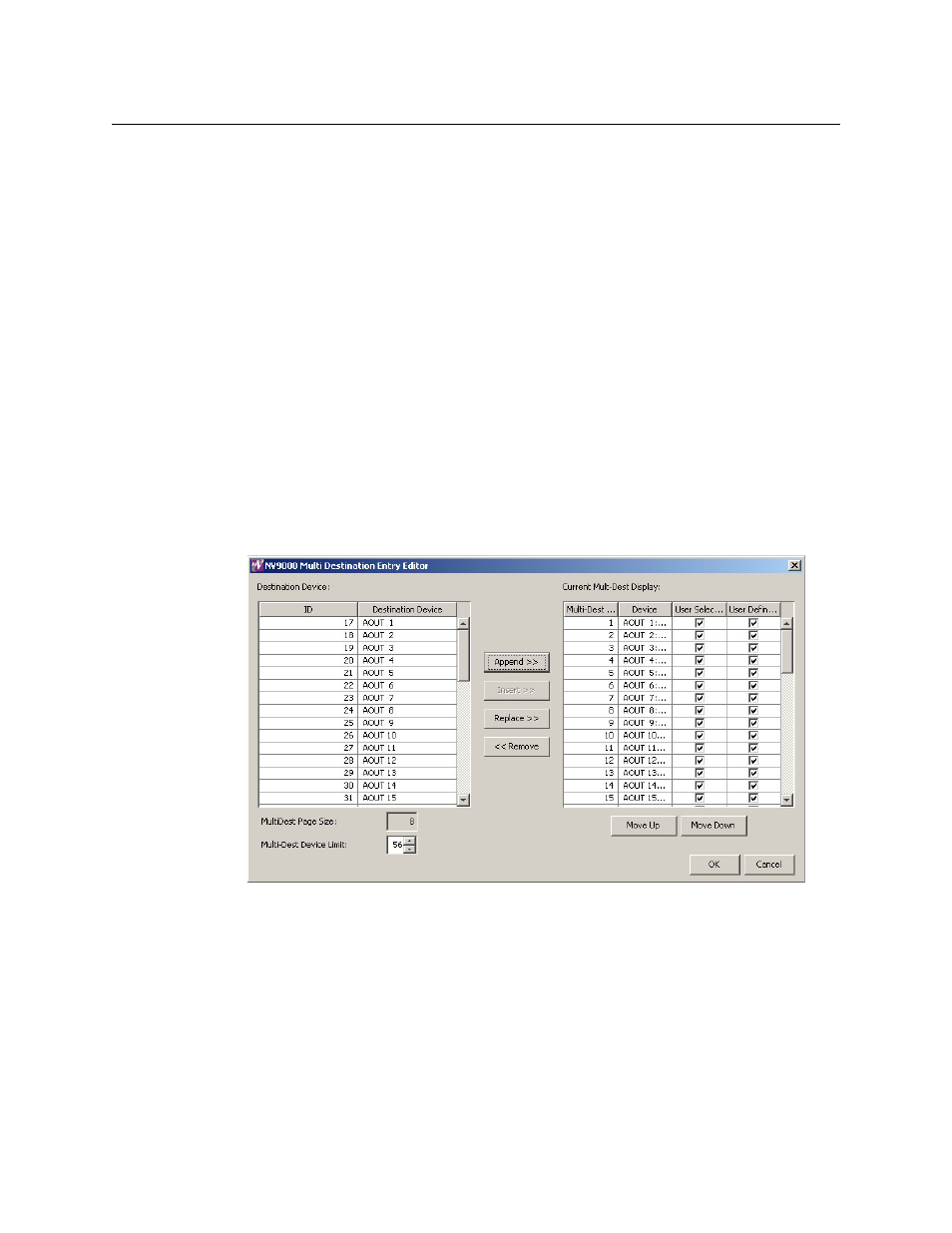
2 Click ‘Edit Multi-Dest Devices’. The multi-destination entry editor appears:
On the left is a list of all destinations defined in the NV9000 system. On the right is a table of the
MD destinations you are defining. The number of rows in this table is equal to the maximum
number of MD destinations your configuration allows.
To define an MD destination, select a destination on the left and copy it, using either the
‘Append’ button, the ‘Insert’ button, or the ‘Replace’ button, to the right.
The ‘Remove’ button removes highlighted MD destinations from the right.
At the bottom right, are ‘Move Up’ and ‘Move Down’ buttons. You can use these to adjust the
position in the list of any MD destination.