Grass Valley NV9000-SE v.5.0 User Manual
Page 356
338
Control Panels
NV9654
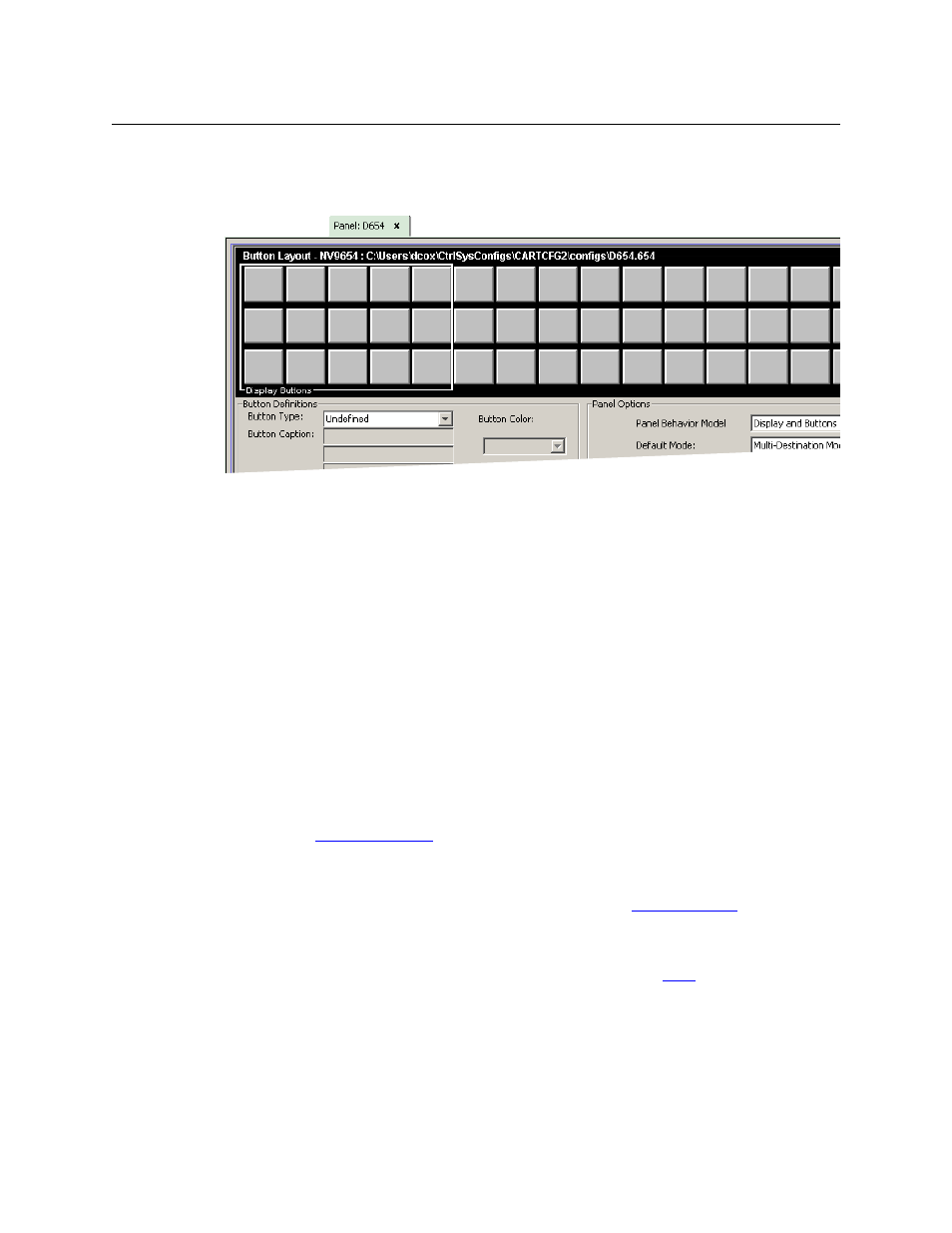
The previous ilustration showed the configuration page set up for ‘All Buttons’ mode. The panel
can also be configured in ‘Display and Buttons’ mode, in which case the “display” section of the
panel graphic is delineated by a white line on the configuration page:
The display section is the 5×3 array of buttons at the left.
Regions of the Configuration Page
There are 5 main regions:
•
The NV9654 panel image.
The NV9654 has 54 LCD buttons in an 18×3 array. Click on a button to assign a function to it.
In some cases, you can click or double-click a button to execute the button function. Dou-
ble-clicking a ‘Navigate’ button, for instance, causes the button’s “subpage” to appear.
Buttons can be illuminated in several colors: green, amber, yellow, red, blue, purple, and
grey. There are 3 levels of illumination: high tally (bright), low tally (muted) and off.
Buttons in the 5×3 display section are always white (if the display is enabled). Operators can
turn the display on and off. Configurers may assign button functions to the buttons of the
display section for those occasions when the operator has turned the display off.
•
Button definition section.
In this section, configurers make button assignments, using its pull-down menus and text
fields. See
, following.
•
Button page table.
This section displays a list of the individual pages of the tree structure. The button page at
the top of the list (or root of the tree) is called “Default.” See
•
GPIO definitions.
In this section, configurers may define GPIO logic. The control panel has a rear connector
that provides 4 relay outputs and 8 optically isolated inputs. See
on page 197. (Note
that the graphical buttons represent connector terminals and not actual buttons.)
•
Panel options.
In this section, configurers may specify the behavioral characteristics of the panel. See the
NV9654 User’s Guide for detailed information.