Connections, Control panels, At the rear – Grass Valley NV9000-SE v.5.0 User Manual
Page 362: One or more routes occurring on specific levels
344
Control Panels
NV9575-VF
The NV9575-VF is a third-party tally interface:
This 1RU device (unlike router control panels) has no controls on its front panel. What it does
have
—
at the rear
—
are 64 relay outputs and 32 optically isolated inputs, typically used for tally
functions.
The NV9575-VF has 6 DB25 connectors on its rear panel that provide connections for the 64
relay outputs, 16 per connector, with 8 pins common. Two additional DB25s provide connec-
tions for the 32 inputs, also 16 per connector with 8 pins common.
Each relay can be configured to switch on a number of conditions:
•
One or more routes occurring on specific levels.
•
Conditions involving output ports (destination, level).
•
A transition on one or more of the NV9575-VF inputs.
Each input (also called a GPI) can be configured to trigger a salvo on a transition from off to on
and to trigger another salvo on a transition from on to off.
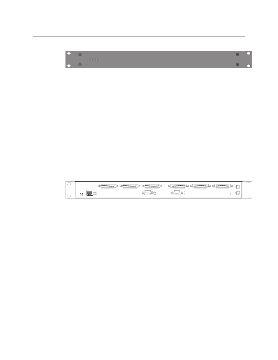
Connections
This is the rear of the tally interface:
The 6 DB25 connectors on its rear panel
—
J1 through J6. J1, J2, J4, and J5
—
provide connec-
tions for the 64 relay outputs, 16 per connector, with 8 pins common. J3 and J6 provide
connections for the 32 inputs, also 16 per connector with 8 pins common.
It also has 2 power connectors, an RJ-45 Ethernet port, two DE9s (remote and console). The DE9s
and the Ethernet port have LED activity indicators.
The ‘remote’ connector is not used. The console connector is used briefly to assign the NV9575-
VF an IP address. The Ethernet connector is the port through which the NV9000 system commu-
nicates with the NV9575-VF after it is set up.
Video
frame
TALLY EXPANDER
POWER
A
B
A
RESET
T
VIDEOFRAME SYSTEMS
GRASS VALLEY, CA
ETHERNET
R T
L C
J1
J2
J3
J4
J5
J6
CONSOLE
REMOTE
12VDC-2.5A
MADE IN USA
B
R
T
R
J1: Outputs
1–16
J2: Outputs
17–32
J3: Inputs
1–16
J4: Outputs
33–48
J5: Outputs
49–64
J6: Inputs
17–32
Remote
Console
Power
Ethernet
Reset