Multi-hop tieline routes, Multi-site tielines, Multi-hop tieline routes multi-site tielines – Grass Valley NV9000-SE v.5.0 User Manual
Page 427
409
NV9000-SE Utilities
User’s Guide
Multi-Hop Tieline Routes
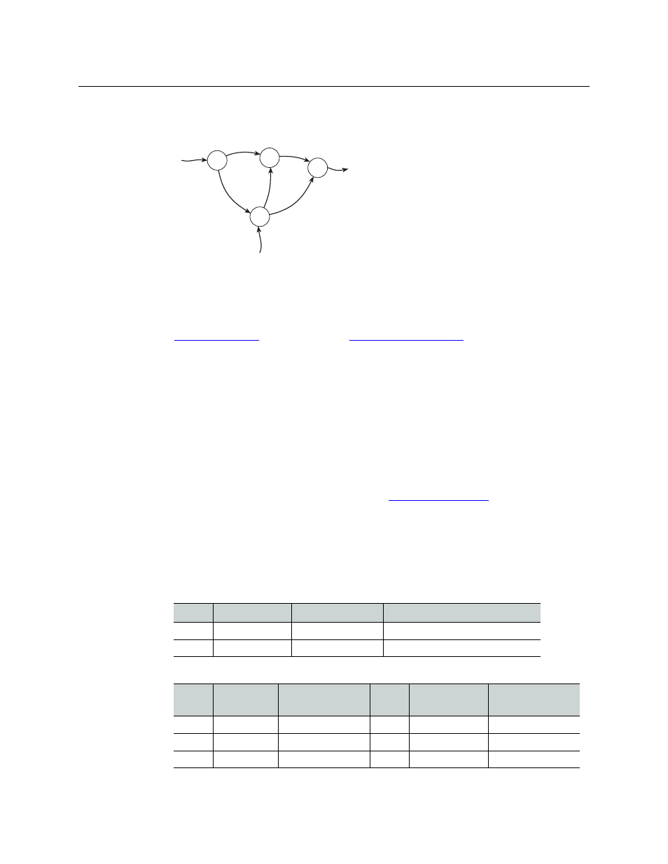
Multi-hop tieline routes are those that comprise more than one simple tieline:
No special configuration need be performed to create multi-hop tielines. It is sufficient to
configure just the individual port connections.
After you have defined all the simple tielines, NV9000-SE Utilities calculates all the multi-hop (or
segmented) tieline paths in the entire network of simple tielines. (These paths can be viewed in
the
(page 432) and the
A take that requires tieline(s) will follow the shortest or lowest cost path from its source device
to its destination device. (You can assign a relative cost value to each simple tieline.)
Multi-Site Tielines
When tielines are defined on more than one NV9000 system controller in a router control
system, we say that the tielines are multi-site tielines. That is, tielines routes created in one
NV9000 system controller can use tielines defined in another NV9000 system controller. The
different NV9000s might or might not be in different cities. The tieline definitions in each
NV9000 must include definitions for the tielines in (all) the other NV9000s.
This requirement warranted the addition of the
(page 442) where the
different NV9000s can be enumerated.
Certain fields in the tieline tables exist because of the possibility of multi-site tielines. Gener-
ally, customers who do not have multi-site telines can ignore those fields.
If, for instance, a system has two system controllers, A and B, and 3 shared tielines, the following
table data might exist:
•
The ‘Control System’ table (in system controller A):
•
The ‘Tieline2’ table (in system controller A):
1
2
5
3
4
devices
devices
devices
A
B
C
D
What “multi-hop” implies is that you can route
a source from a router (point A) to a router not
directly connected to A (such as point C) in a
single take. There are several paths from A to C:
the NV9000 control software chooses the best
path (usually the shortest and of the least cost).
ID
Name
IP Address
Description
1
Local
127.0.0.1
Local control system (A)
2
System B
192.168.102.1
Remote control system (B)
ID
Control
System
Control System’s
Tieline2 ID
Cost
Name
Description
1
Local
1
1
A tieline 1
2
System B
1
1
B tieline 1
3
Local
3
1
A tieline 2