Dell POWEREDGE M1000E User Manual
Page 170
170
Using the CLI
•
the interface type tag followed by the Unit# followed by a / symbol, then
the Slot# followed by a / symbol, and then the Port#. For example,
gi2/0/10 identifies the gigabit port 10 in slot 0 within the second unit on
a non-blade switch. Table 2-4 below lists the supported interface type
tags.
•
Unit
# — The unit number is greater than 1 only in a stacking solution
where a number of switches are stacked to form a virtual switch. In this
case, the Unit# indicates the logical position of the switch in a stack. The
range is 1–12. The unit value is 1 for standalone switches.
•
Slot
# — on page 1564
•
Port
# — The port number is an integer number assigned to the physical
port on the switch and corresponds to the lexan printed next to the port on
the front or back panel. Ports are numbered from 1 to the maximum
number of ports available on the switch, typically 24 or 48.
Within this document, the tag interface–id refers to an interface identifier
that follows the naming convention above.
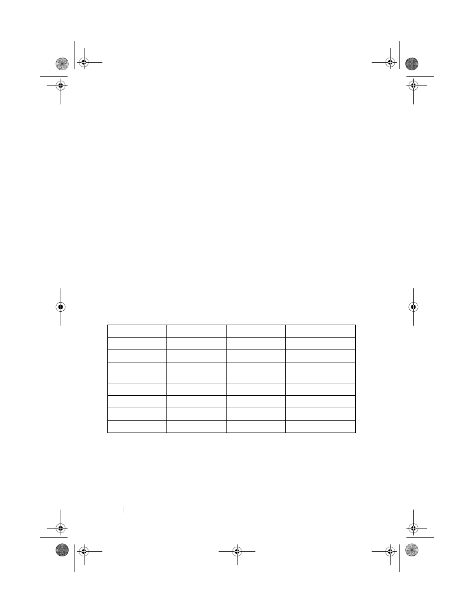
Table 2-4. Interface Identifiers
When listed in command line output, gigabit Ethernet interfaces are
preceded by the characters
Gi
, and ten-gigabit Ethernet interfaces are
preceded by
Te
, as shown in the examples below.
Interface Type
Long Form
Short Form
Identifier
Fast Ethernet
fastethernet
fa
unit/slot/port
Gigabit Ethernet
gigabitethernet
gi
unit/slot/port
10-Gigabit
Ethernet
tengigabitethernet te
unit/slot/port
Loopback
loopback
lo
loopback-id (0-7)
Port Channel
port-channel
po
port-channel-number
Tunnel
tunnel
tu
tunnel-id (0-7)
Vlan
vlan
vl
vlan-id 1-4093)
2CSPC4.XModular-SWUM200.book Page 170 Thursday, March 10, 2011 11:18 AM