Echelon LonMaker User Manual
Page 373
LonMaker User’s Guide
357
name, right-click the channel shape, click Properties on the shortcut menu, enter the new channel
name in the Name box, and then click OK.
5. Define and commission (optional) the analog input and digital output LonPoint devices.
a. Enable one-click device creation. Open the LonMaker menu and then click LonMaker
Options. Select Device from the Options Category list. Select the Enable Automatic
Channel Selection check box.
b. To commission the devices, under New Device Options, select the Commission after
Creation check box Prompt for Device State.
c. Drag an AI-10 device shape
from the LonPoint Shapes 3.0 stencil to the drawing.
Press the service pin on the device if you are commissioning it.
d. Drag a DO-10 device shape
from the LonPoint Shapes 3.0 stencil to the drawing.
Press the service pin on the device if you are commissioning it.
6. Assign Functional Blocks to the LonPoint Devices.
a. Enable one-click functional block creation. Open the LonMaker menu and then click
LonMaker Options. Select Functional Block from the Options Category list. Select the
Enable Automatic Device Selection check box.
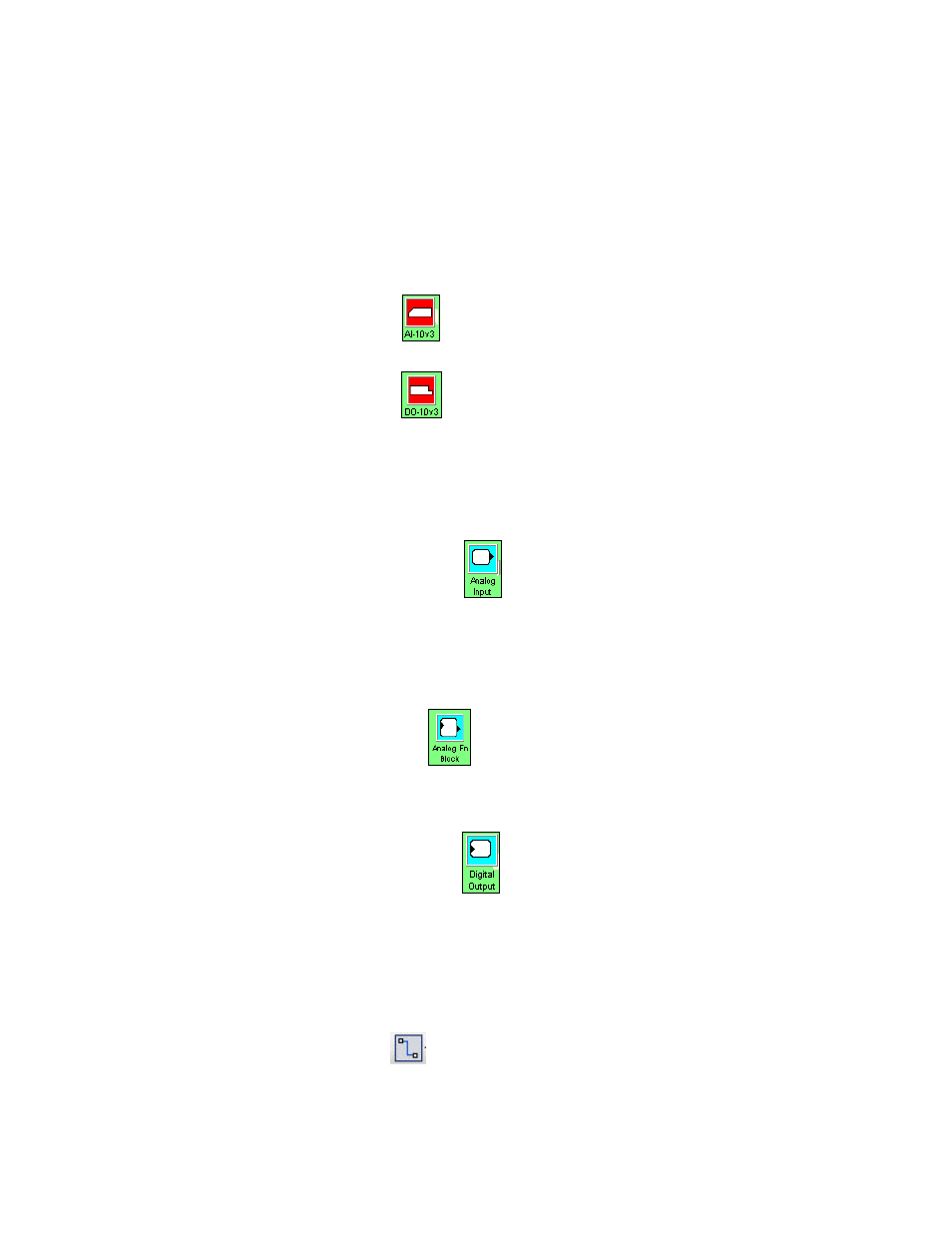
b. Drag an analog input functional block
from the LonPoint Shapes 3.0 stencil to the
drawing. The functional block will automatically be assigned to the AI-10 device.
This functional block represents the temperature sensor. Optionally, you can rename the
functional block to “Analog Temperature Sensor” or to another descriptive name. Right-click
the functional block, select Properties from the shortcut menu, enter the desired name in the
FB Name box, and then click OK.
c. Drag an analog functional block
from the LonPoint Shapes 3.0 stencil to the drawing.
The functional block will automatically be assigned to the AI-10 device. This functional
block represents the thermostat. Optionally, you can rename the functional block to “Analog
Thermostat” or to another descriptive name.
d. Drag a digital output functional block
from the LonPoint Shapes 3.0 stencil to the
drawing. The functional block will automatically be assigned to the DO-10 device. This
functional block represents the exhaust fan switch. Optionally, you can rename the functional
block to “Digital Exhaust Fan Switch” or to another descriptive name.
7. Connect the network variables.
a. Connect the temperature sensor (AI) functional block to the thermostat (AFB) functional
block.
Select the Connector tool
on the Visio Standard toolbar. Point to the Analog network
variable on the temperature sensor (AI) functional block until a red square appears around the