Echelon LonMaker User Manual
Page 204
188
Monitoring and Controlling Networks
You can use high-end HMI tools, such as Wonderware’s InTouch or Intellution FIX, to represent more
complex types of network interactions. These tools are developed with a scripting language tuned to
specifically address HMI tasks. In addition, these tools offer components that provide reporting and
analysis, history, alarm logging, event handling, and Internet-enabling.
To create a simple HMI with Data Point and Visio shapes, you do the following:
1. Add Data Point shapes to your drawing as described in Adding and Monitoring a Data Point
Shape. You use the Data Point shapes to monitor and control data points.
2. Add Visio shapes to your drawing (you can use any Visio shape—the previous lighting HMI
example uses shapes in the Visio Basic Shapes stencil). You use the Visio shapes to read and write
to the Data Point shapes.
3. Customize the ShapeSheets of the Data Point and Visio shapes so that they can interact with each
other. You insert functions in the ShapeSheets that are executed when a supported event occurs
(for example, when a Visio shape is clicked or the value in a Data Point shape changes). You can
easily create functions using Add-Ons, Macros, or both. For more information on customizing
ShapeSheets go to
The following two sections describe how to customize the ShapeSheets of the Data Point and Visio
shapes using the previous lighting HMI example. The first section explains how to make a Visio shape
write a value to a Data Point shape; the second explains how to make a Visio shape read a value from
the Data Point shape.
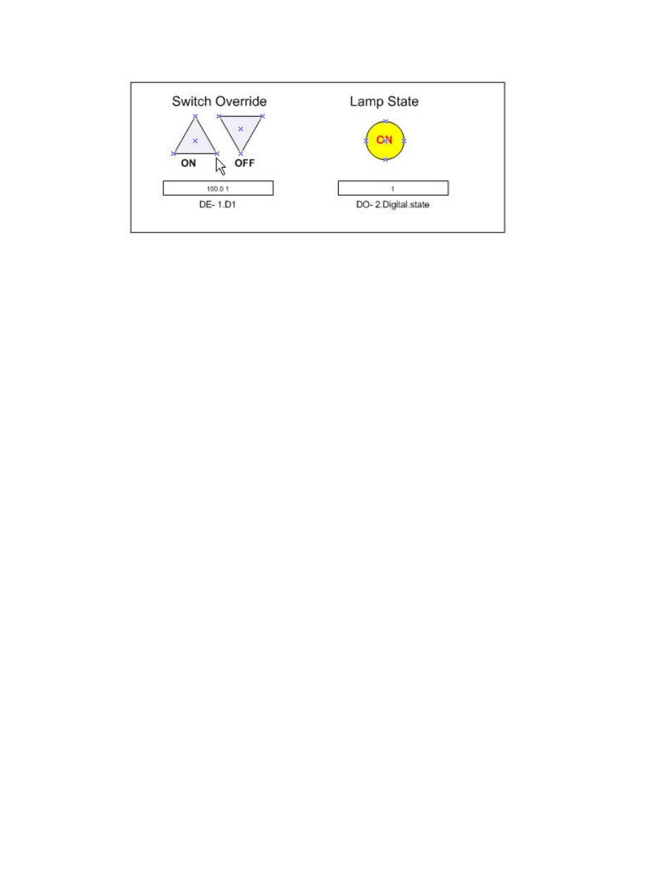
The lighting system that this HMI represents includes the following physical and logical components:
• Digital input/output device.
• Digital input and digital encoder functional blocks. The Digital output network variable on the
digital input functional block is connected to the D1 input network variable on the digital encoder
functional block.
• A digital output functional block. The Digital_Out output network variable on the digital encoder
functional block is connected to the Digital input network variable on the digital output functional
block.
• A Data Point shape that controls the D1 input network variable on the digital encoder functional
block.
• A Data Point shape that monitors the Feedback output network variable on the digital output
functional block.
• Two Visio shapes that write to the Data Point shape that controls the D1 input network variable.
• One Visio shape that reads the Data Point shape that monitors the Feedback output network
variable.