Echelon LonMaker User Manual
Page 266
250 Maintaining
Networks
7. Exit the LonMaker drawing of the source network.
8. Back up the destination LonMaker network design following the steps in Manually Backing Up a
LonMaker Network Design in this chapter. You can use the backup to restore the network if the
merge process fails for any reason. If a failure occurs during the merge process, the destination
network will be left in a partially merged state and the LonMaker tool will not let you access the
network. To return the network to its original state, restore the backup of the destination network.
9. Ensure that the device interface (XIF) files for all the devices in the source network are available
in the directory specified in the XIF Search Path field in the network properties: Device options
category.
10. Open the destination LonMaker network design following the steps described in Opening an
Existing LonMaker Network Design in Chapter 3, Getting Started.
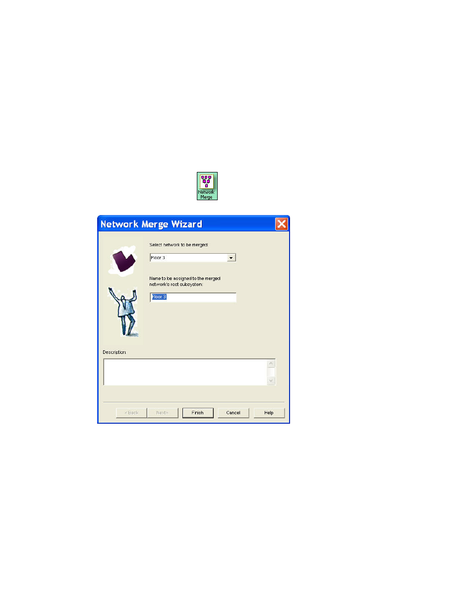
11. Drag the Network Merge shape
from the LonMaker Basic Stencil to a subsystem page
within the destination network. The Network Merge Wizard opens.
12. Select the source network you exported in steps 4–6 from the Select Network to be Merged list.
This list contains only those networks that have been exported using the Merge Export Utility.
13. Enter a name for the root subsystem of the source network in the Name to Be Assigned box.
14. Click Finish to begin the network merge. The source network and its underlying subsystem
hierarchy will be added as a new subsystem. The merge process copies all documents from the
source drawing directory into the destination drawing directory and renames them, as required.
The shapes are then scanned and added to the destination network database. A network merge
status window appears and indicates the progress of the merge.