Fluke Networks CertiFiber Pro Users Manual User Manual
Page 319
Chapter 12: How to Diagnose Problems in Fiber Links
Causes of OTDR Test Failures
297
Table 15.
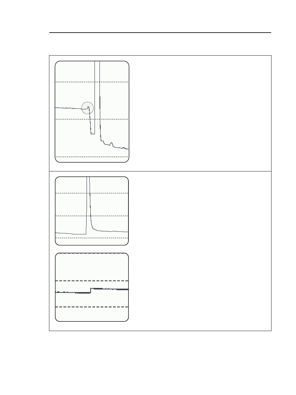
Can be caused by very sharp bend, a crack,
or a mechanical splice with high loss. If the
event is a bend, it usually has higher loss at a
longer wavelength. Use a visual fault locator
to verify the problem.
This example shows a sharp bend that occurs
before a connector.
A gainer does not cause a test failure unless
it exceeds a limit, but it can indicate a
problem such as a connection or splice
between mismatched fibers (different
backscatter coefficients, core sizes,
numerical apertures, or other parameters).
The top example shows a smaller core size
connected to a larger core size. If you do a
test from the other end, you would see a
large reflective event with more loss than a
connector should have.
The bottom example shows a splice between
smaller and larger core sizes.
Causes of OTDR Test Failures (continued)
GPU32.EPS
The trace shows a small reflective event with
high loss. Can possibly show as an end event
though it occurs before the end of the link.
GPU50.EPS
The trace shows an apparent increase in
optical power (a “gainer”).
(continued)