Figure 518 – Brocade Network Advisor SAN User Manual v12.3.0 User Manual
Page 1259
Brocade Network Advisor SAN User Manual
1207
53-1003154-01
Predefined flow definition templates
29
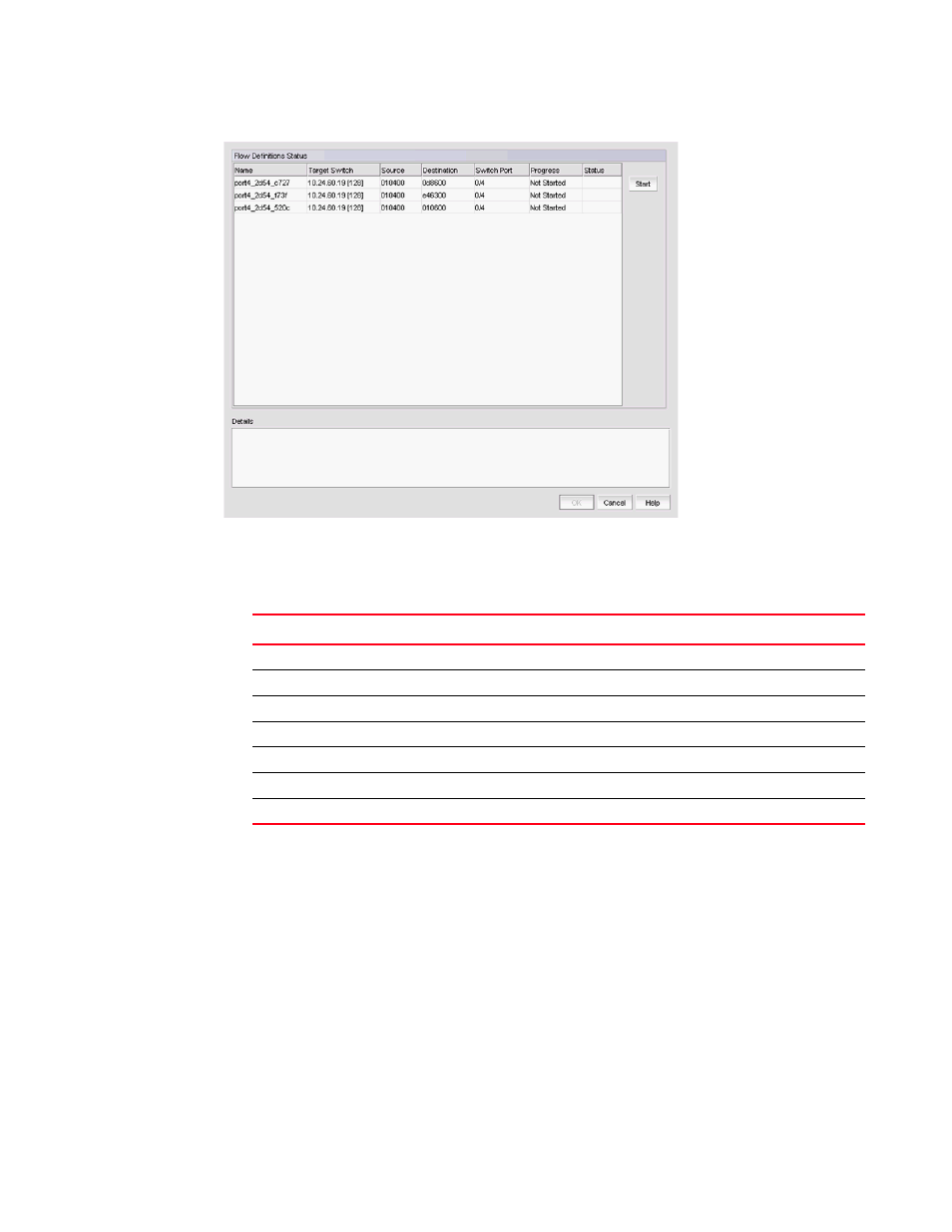
FIGURE 518
Deployment Status dialog box
describes the data displayed in the Flow Definitions Status table.
9. Select one or more flow definitions in the Flow Definitions Status table and click Start.
10. View additional details for a deployed flow definition by selecting the flow defintion in the Flow
Definitions Status table.
The reason for sucess or failure displays in the Details area.
To review the sub-flow data for the selected flow, refer to
TABLE 99
Flows Definitions table fields and components
Field and components
Description
Name
The user-defined name for the flow definition.
Target Switch
The switch on which you created the flow definition.
Source
The source identifiers defined in the flow definition.
Destination
The port number of the destination device defined in the flow definition.
Switch Port
The switch port defined in the flow definition.
Progress
The progress of the flow (Not Started, In Progress, or Completed).
Status
The status of the flow (empty if not started; otherwise, Sucess or Failed).