Brocade Network Advisor SAN User Manual v12.3.0 User Manual
Page 1258
1206
Brocade Network Advisor SAN User Manual
53-1003154-01
Predefined flow definition templates
29
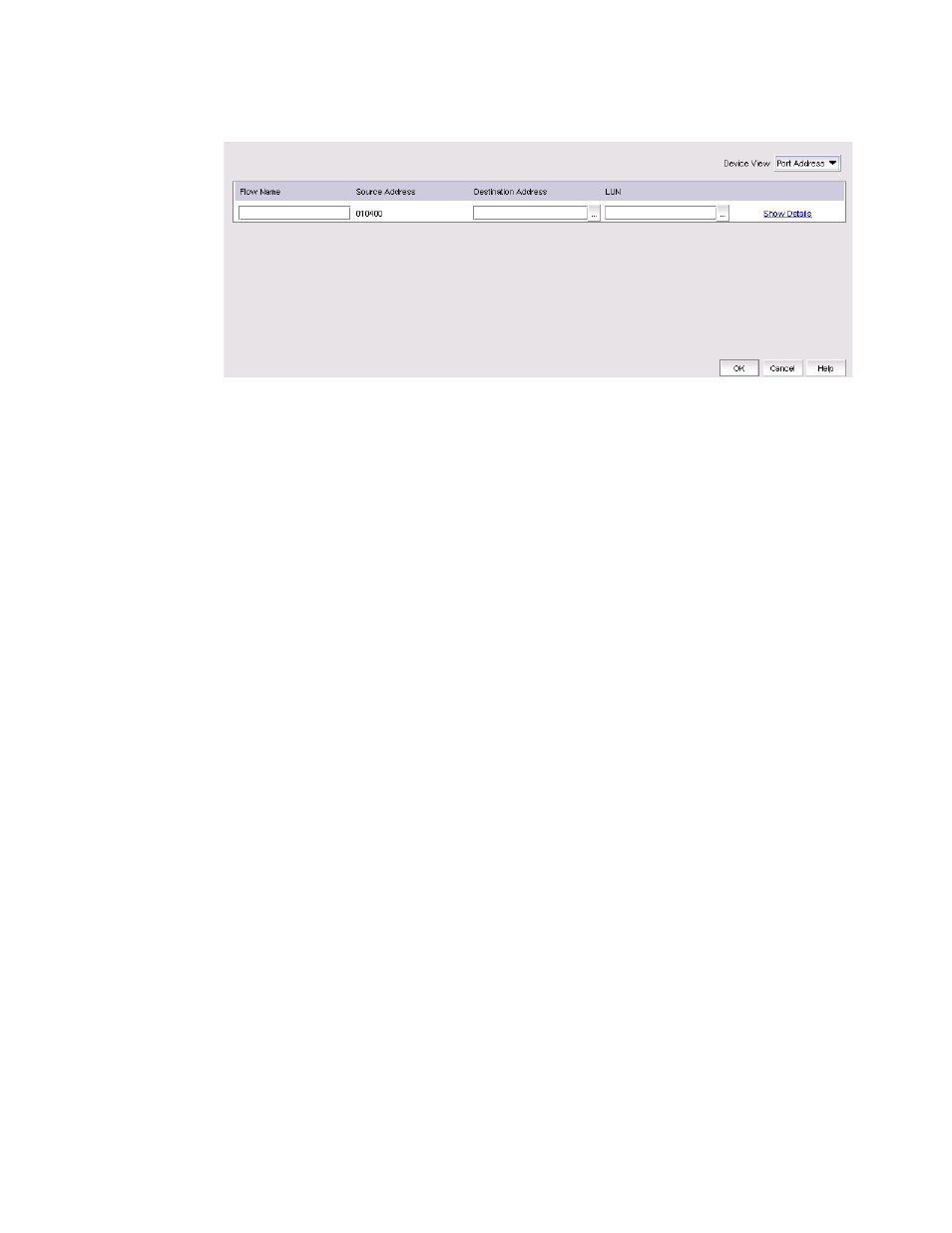
FIGURE 517
Sample Add Flow -
predefined_monitor
dialog box
3. Enter a name for the flow definition in the Flow Name field.
4. Select one of the following format options from the Device View list:
•
Port Address (port ID) — Select to display the source and destination device address using
the port ID.
•
WWN (world wide name) — Select to display the source and destination device address
using the port WWN.
5. Enter the port ID or WWN of the source port in the Source field or click the ellipsis button to
select a port from the list.
Enter an asterisk (*) to use any port. To select the source port from a list, refer to
end device port from a list of available device ports”
6. Enter the port ID or WWN of the destination port in the Destination field or click the ellipsis
button to select a port from the list.
Enter an asterisk (*) to use any port. To select the destination port from a list, refer to
“Selecting an end device port from a list of available device ports”
7. Click Show Details to view information about the Target Switch, Ingress, and Egress ports
based on the selected port.
This data is not editable. Click Hide Details to hide the Target Switch, Ingress, and Egress port
information.
8. Click OK to deploy the flow definition.
The Deployment Status dialog box displays with a list of all defined flows in the Flow Definitions
Status table, as shown is
.