Meridian America Link/Customer Controlled Routing User Manual
Page 75
Chapter 4: Meridian Link/CCR hardware 57
Meridian Link Release 5C/CCR Release 3C Installation and Upgrade Guide
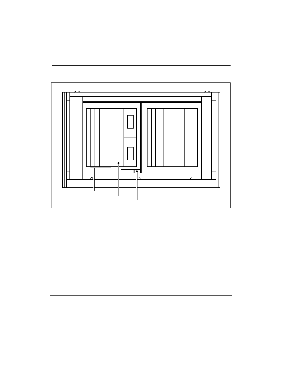
Figure 15
Application ModuleÑrear view
Transition cards
Part of chassis
(cannot be ordered)
M
V
M
E
7
0
5
B
M
V
M
E
7
1
2
M
Power sense card
J8
J9
Meridian Link Module
CCR/Co-resident Module
M
V
M
E
7
0
5
B
M
V
M
E
7
1
2
M
or
A
or
AM
N
T
6
D
5
1
A
A
or
A
or
AM
As shown in Figure 15, slots at the rear of the Application Module house the
following cards:
¥
MVME712M (double-width), MVME712A, or MVME712AM
transition card
¥
MVME705B transition card
¥
NT6D51AA transition card (for CCR/Co-resident Module)
The power sense card and the adapter board are mounted in the rear of the
Application Module, either on the I/O subpanel, which is installed in the
AEM I/O panel in older installations, or on a central bracket at the bottom
of the AEM.