Shroud row, Common equipment slots peripheral equipment slots – Meridian America Link/Customer Controlled Routing User Manual
Page 209
Chapter 9: Meridian Link/CCR interface cabling 191
Meridian Link Release 5C/CCR Release 3C Installation and Upgrade Guide
Table 65
NT8D11 cable connections (fully expanded configuration) (continued)
I/O panel connector
port
Backplane cable
connector
Backplane slot
position
G (new cable)
G-1
G-2
G-3
L6-1
L6-2
L6-3
H
H-1
H-2
H-3
L7-1
L7-2
L7-3
K
K-1
K-2
K-3
L8-1
L8-2
L8-3
L (new cable)
L-1
L-2
L-3
L9-1
L9-2
L9-3
Ñ end Ñ
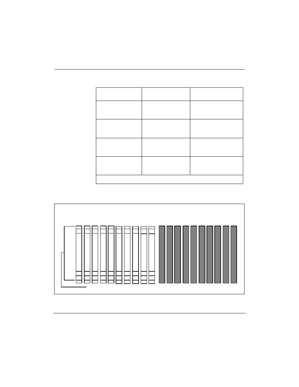
Figure 50
NT8D11 backplane cable designations (fully expanded configuration)
Shroud row
1
2
3
L9 L8 L7 L6 L5 L4 L3 L2 L1 L0 C9 C8 C7 C6 C5 C4 C3 C2 C1 C0
K-2
K-3
K-1
A-1
A-2
A-3
B-1
B-2
B-3
C-1
C-2
C-3
E-1
E-2
E-3
F-1
F-2
F-3
H-1
H-2
H-3
Common equipment slots
Peripheral equipment slots
D-1
D-2
D-3
G-1
G-2
G-3
L-1
L-2
L-3