Meridian America Link/Customer Controlled Routing User Manual
Page 231
Chapter 9: Meridian Link/CCR interface cabling 213
Meridian Link Release 5C/CCR Release 3C Installation and Upgrade Guide
3
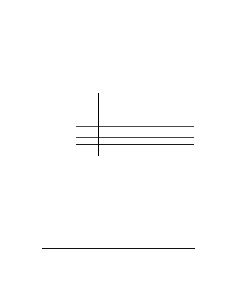
Connect the ports of cable NT1R03AA to external equipment, as
described in Table 72 and shown in Figure 55. For example, connect
port 1 of the NT1R03AA cable to the console, using a customer-
supplied cable.
Table 72
Options 21Ð81 IPE Module external connections (NT1R03AA cable)
NT1R03AA
port
External equipment
External cable or reference
1
console
NT1R03D or customer-supplied
cable. See Table 74 for pinout.
3
conshare
See ÒSDI cabling (Options 21Ð81
IPE Module).Ó
5
AML
See ÒESDI/MSDL cabling
(Options 21Ð81 IPE Module).Ó
7
terminal
NT1R03D
Ethernet
Ethernet LAN
See ÒInstalling Ethernet LAN
support.Ó
4
Connect the ports of cable NT1R03BA to external equipment, as
described in Table 73 and shown in Figure 55. For example, connect
port 2 of the NT1R03BA cable to the external modem, using
extension cable NT1R03HF.