Connector panel and i/o connectors (option 11) – Meridian America Link/Customer Controlled Routing User Manual
Page 60
42 Chapter 4: Meridian Link/CCR hardware
553-3202-210 Standard October 1998
Connector panel and I/O connectors (Option 11)
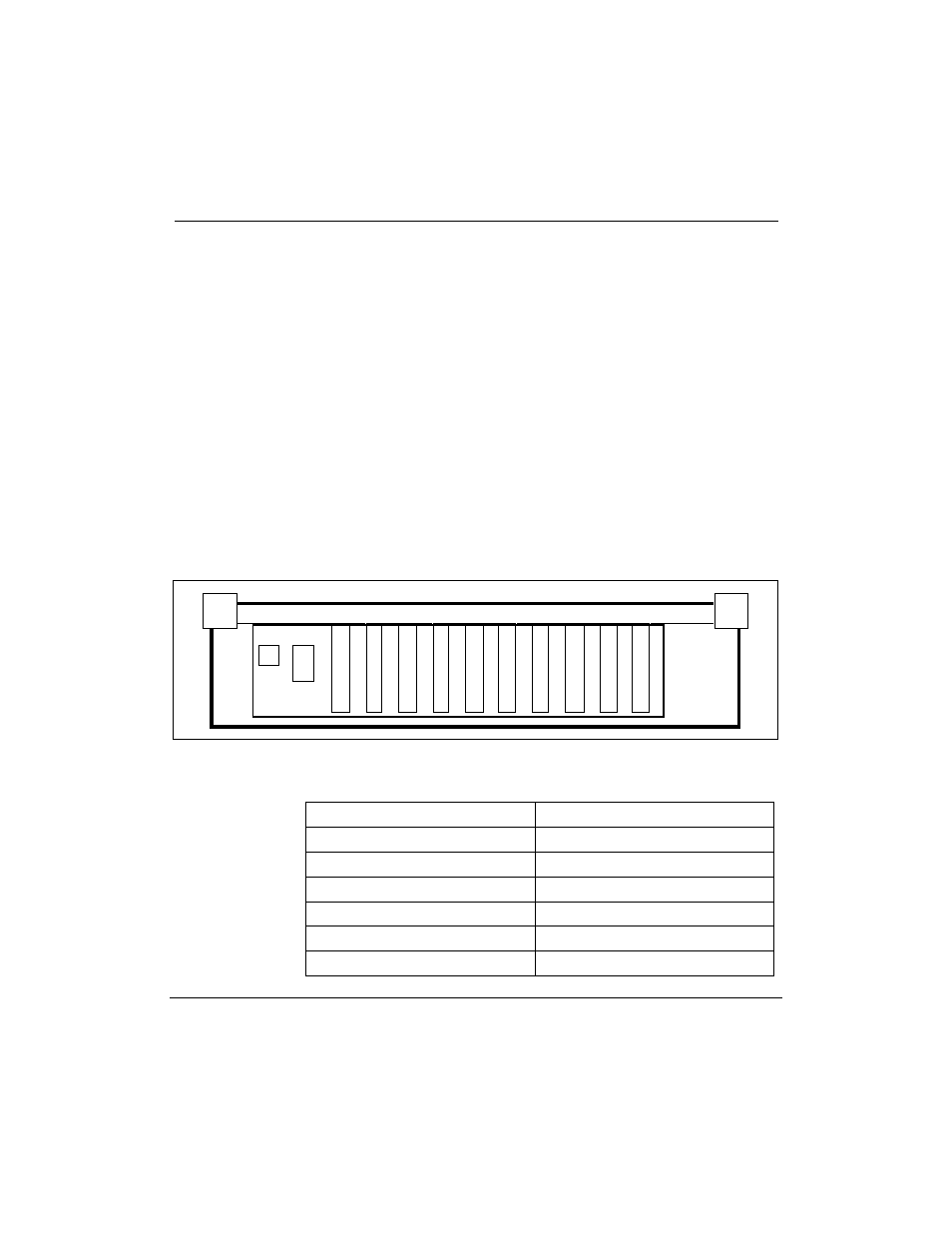
Underneath each cabinet of the Option 11 is a connector panel with ten
numbered connector ports. Each connector port connects to the
corresponding numbered slot directly above it, inside the cabinet. Figure 8
shows the connector panel for the main cabinet, and Figure 9 shows the
connector panel for the expansion cabinet.
The I/O connectors for the IPE Module installed in an Option 11 system are
standard, shielded, 50-pin tip-ring-type connector ports on the connector
panel, which is located under the cabinet containing the module. The
connector ports used depend on the slots occupied by the IPE Module.
Tables 5 and 6 show the connector ports used for each possible location of
the IPE Module. Figure 6 shows the IPE Module installed in slots 5, 6, and
7 of an Option 11 main cabinet. Table 5 shows that the cables are connected
to connector ports J5 and J7.
Figure 8
Option 11 connector panel (main cabinet)
0
1
2
3
4
5
6
7
8
9
¥
Table 5
Option 11 IPE Module connectors used (main cabinet)
Slots occupied by IPE Module
Connector ports used
2, 3, 4
J2 and J4
3, 4, 5
J3 and J5
4, 5, 6
J4 and J6
5, 6, 7
J5 and J7
6, 7, 8
J6 and J8
7, 8, 9
J7 and J9