Meridian America Link/Customer Controlled Routing User Manual
Page 309
Chapter 11: Peripheral device cabling interface 291
Meridian Link Release 5C/CCR Release 3C Installation and Upgrade Guide
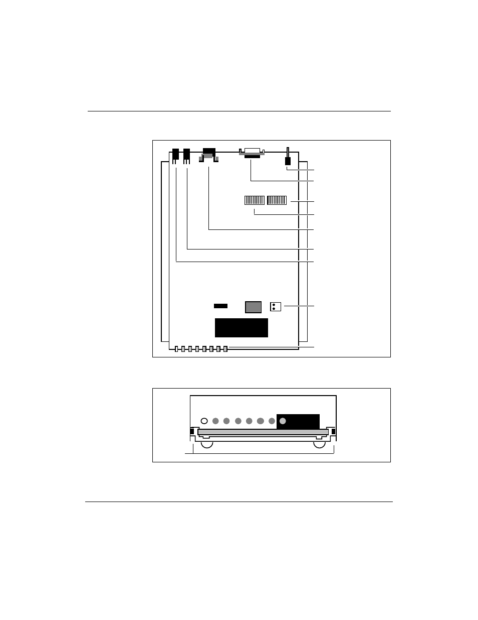
Figure 90
Ven-Tel 2400 Plus II modemÑswitch locations
¥
White and red
indicator lights
Line in
Line out
Power cable socket
RS-232/EIA socket
Power switch
The Reset button
connected to the
faceplate plugs into
this connector
¥
SW1 switch (red)
¥
¥
¥
¥
¥
¥
SW2 switch (red)
¥
Figure 91
Ven-Tel 9600 Plus modemÑopening the modem
¥
Modem Computer Board
Top
Bottom
Grooves
¥