Meridian America Link/Customer Controlled Routing User Manual
Page 152
134 Chapter 8: Hardware installation procedures
553-3202-210 Standard October 1998
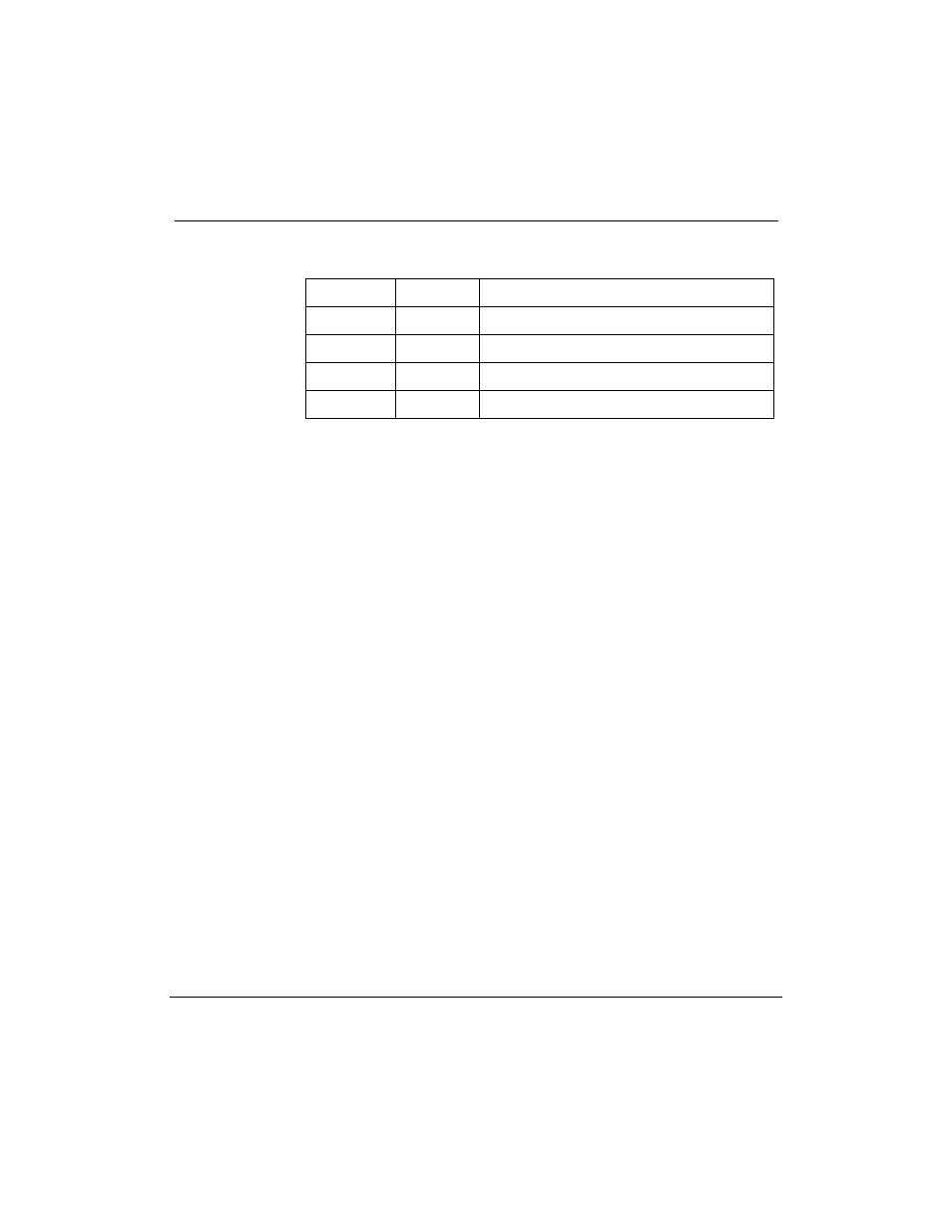
Table 36
Default DCE/DTE settings for MVME712M transition card
Serial Port
Setting
Use
SP1
DCE
Console
SP2
DTE
External Modem
SP3
DTE
Conshare
SP4
DTE
Meridian Mail Link (Meridian Link only)
¥
The NT6D51AA card, if present, has no option settings.
10
Reconnect the ribbon cables to the transition cards as follows:
¥
Connect the cable from the MVME333-2 XCC card to the
MVME705B transition card.
¥
Connect the cable from the P2 adapter board to the MVME712
transition card.
11
Reinstall the transition cards in the Application Module. Push the
cards in until the faceplates are flush with the front of the module.
12
Install the screws at the top and bottom of the transition card
faceplates.
13
Reinstall the Application Module (if necessary) as follows:
¥
Hold the Application Module by the bar on the top and position it
in the AEM. Slide the unit into the AEM.
¥
Tighten the four screws on the front of the Application Module.
¥
Position the I/O subpanel, universal I/O panel, or generic I/O
panel at the rear of the Application Module. Tighten or reinstall
the screws that secure the panel.
¥
Attach the orange logic-return ground wire to the screw on the
terminal block at the bottom of the AEM.
¥
Connect the yellow and gray cable from the power sense card to
the appropriate plug on the power monitor.
If the Application Module is on the right side of the AEM (from
the rear view), the cable connects to P1 on the power monitor. If
the Application Module is on the left side of the AEM, the cable
connects to P2.