Segment 3 segment 2 segment 1 segment 0 – Meridian America Link/Customer Controlled Routing User Manual
Page 220
202 Chapter 9: Meridian Link/CCR interface cabling
553-3202-210 Standard October 1998
Table 68
NT8D37 cable connections (fully expanded configuration) (continued)
I/O panel connector
port
Backplane cable
connector
Backplane slot
position
T
T-1
L14-1
T-2
L14-2
T-3
L14-3
U (new cable)
U-1
L15-1
U-2
L15-2
U-3
L15-3
Ñ end Ñ
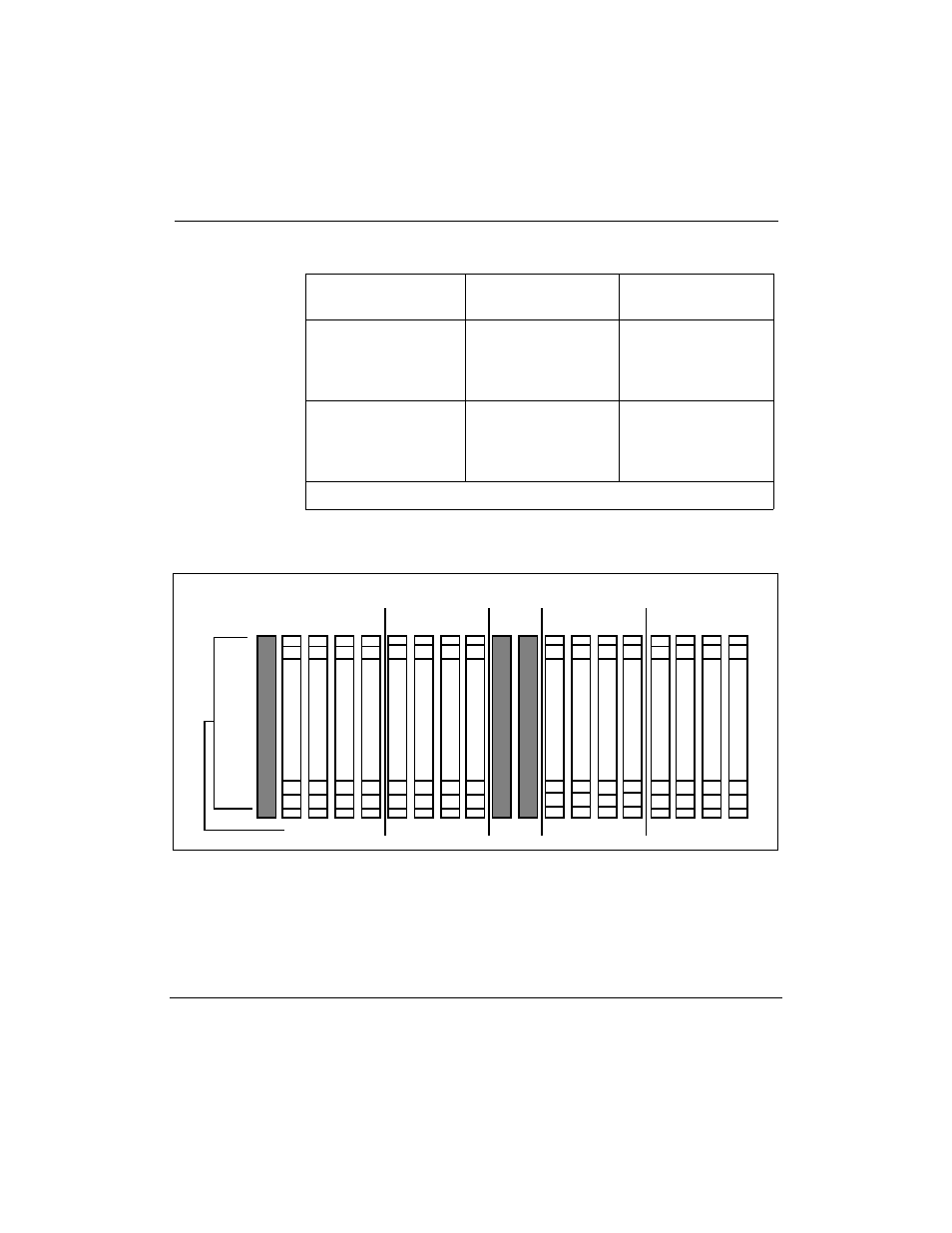
Figure 53
NT8D37 backplane cable designations (fully expanded configuration)
Segment 3
Segment 2
Segment 1
Segment 0
S-1
S-2
L16 L15 L14 L13 L12
T-1
R-1
R-2
R-3
M-2
L-3
L-1
K-1
M-3
M-1
L-2
K-2
K-3
S-1
L11 L10 L9 L8
Shroud Row
1
2
3
L7 L6 L5 L4
E-1
E-2
E-3
F-1
F-2
F-3
G-1
G-2
G-3
S-3
T-2
T-3
U-1
U-2
U-3
S-2
N-1
N-2
N-3
H-1
H-2
H-3
L3 L2 L1 L0
A-1
A-2
A-3
B-1
B-2
B-3
D-1
D-2
D-3
C-1
C-2
C-3