Meridian America Link/Customer Controlled Routing User Manual
Page 151
Chapter 8: Hardware installation procedures 133
Meridian Link Release 5C/CCR Release 3C Installation and Upgrade Guide
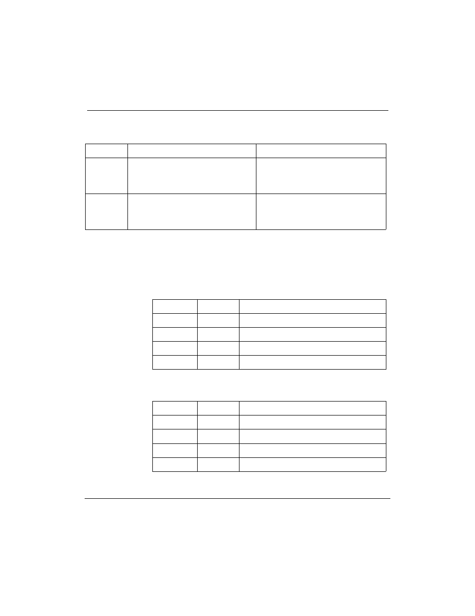
Table 33
MVME705B jumper settings and cable connections
Serial port
DCE mode
DTE mode
SP1
On header K6, place jumpers over
pins 3Р4, 7Р8, 9Р10
Plug the I/O cable into P14
On header K6, place jumpers over
pins 1Р2, 5Р6
Plug the I/O cable into P13
SP3
On header K5, place jumpers over
pins 3Р4, 7Р8, 9Р10
Plug the I/O cable into P12
On header K5, place jumpers over
pins 1Р2, 5Р6
Plug the I/O cable into P11
¥
Check the jumpers on the MVME712 transition card as indicated
in Figure 36 (for MVME712AM), Figure 37 (for MVME712A) or
Figure 38 (for MVME712M). Tables 34 through 36 show the
default setups for the transition cards.
Table 34
Default DCE/DTE settings for MVME712AM transition card
Serial Port
Setting
Use
SP1
DCE
Console
SP2
Ñ
Internal Modem
SP3
DCE
Conshare
SP4
DCE
Meridian Mail Link (Meridian Link only)
Table 35
Default DCE/DTE settings for MVME712A transition card
Serial Port
Setting
Use
SP1
DCE
Console
SP2
DCE
External Modem
SP3
DCE
Conshare
SP4
DCE
Meridian Mail Link (Meridian Link only)