Left i/o panel, Right i/o panel – Meridian America Link/Customer Controlled Routing User Manual
Page 229
Chapter 9: Meridian Link/CCR interface cabling 211
Meridian Link Release 5C/CCR Release 3C Installation and Upgrade Guide
Use the following procedure to cable to external equipment.
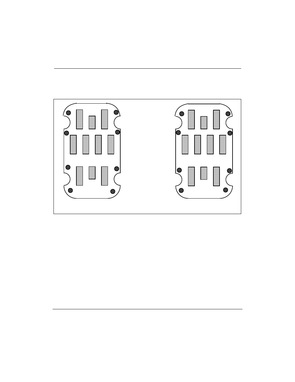
Figure 56
IPE shelf I/O panels (Options 21Ð81)
Left I/O panel
S
R
N
M
U
T
L
K
Right I/O panel
F
E
D
C
H
G
A
B
J4
J2
J5
J3
1
Ensure that the power for the IPE Module is turned off.
2
Connect the NT1R03AA and NT1R03BA octopus cables to the I/O
panel; the specific connectors depend on the location of the IPE
Module. Tables 70 and 71 list the connectors to use for various
locations of the IPE Module. For example, if the IPE Module is in
slots 0 through 3, connect the NT1R03AA cable to connector D, and
the NT1R03BA cable to connector A.