Meridian America Link/Customer Controlled Routing User Manual
Page 269
Chapter 9: Meridian Link/CCR interface cabling 251
Meridian Link Release 5C/CCR Release 3C Installation and Upgrade Guide
SDI Paddle Board cabling (Application Module)
The NT8D41 SDI Paddle Board connects to the I/O panel in the Meridian 1
through an NT8D84AA cable (see Table 88). From the Meridian 1 I/O
panel or SDI Paddle Board on the Meridian 1, an NT7D46 cable (see Table
81 for lengths and specific codes) connects to the Application Module at
¥
J8 on the I/O subpanel
¥
SDI LINK port on the universal I/O panel
¥
card 1 conn 3 on the generic I/O panel
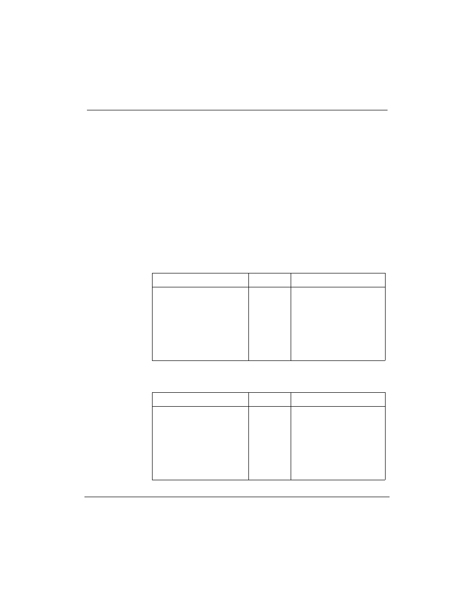
The NT7D46 cable has a 9-pin male connector for the Meridian 1 and a 9-pin
female connector for the Application Module. Table 86 lists the pin
assignments required for the cable.
Table 86
NT7D46 cable pinouts
Meridian 1
Signal
AM (J8)
2
6
4
9
8
3
1
7
TXD
RXD
RTS
CTS
DSR
LRTN
DCD
DTR
3
2
7
8
6
5
1
4
Table 87
NT8D84AA cable pinout
10-pin connector
Signal
DB9 connector
2
6
4
9
8
3
1
7
TXD
RXD
RTS
CTS
DSR
LRTN
DCD
DTR
2
6
4
9
8
3
1
7