Meridian America Link/Customer Controlled Routing User Manual
Page 266
248 Chapter 9: Meridian Link/CCR interface cabling
553-3202-210 Standard October 1998
System console cabling (Application Module)
As shown in Figures 65Ð74, the system console connects to the MVME712
transition card at
¥
J7 on the I/O subpanel
¥
SYS CONS port on the universal I/O panel
¥
card 1 conn 1 on the generic I/O panel
Use a customer-supplied cable (or an extra NT7D61) with a 9-pin female
and 25-pin male connector from the console to the Application Module.
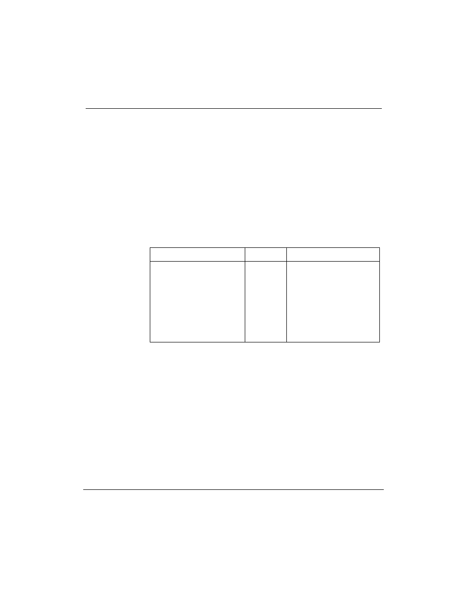
Table 83 lists the pin assignments required for the cable.
Table 83
System console cable pinout
Meridian 1
Signal
AM (J7) 9-pin connector
2
3
4
5
6
7
8
20
1
TXD
RXD
RTS
CTS
DSR
LRTN
DCD
DTR
GND
3
2
7
8
6
5
1
4
9