Meridian America Link/Customer Controlled Routing User Manual
Page 275
Chapter 9: Meridian Link/CCR interface cabling 257
Meridian Link Release 5C/CCR Release 3C Installation and Upgrade Guide
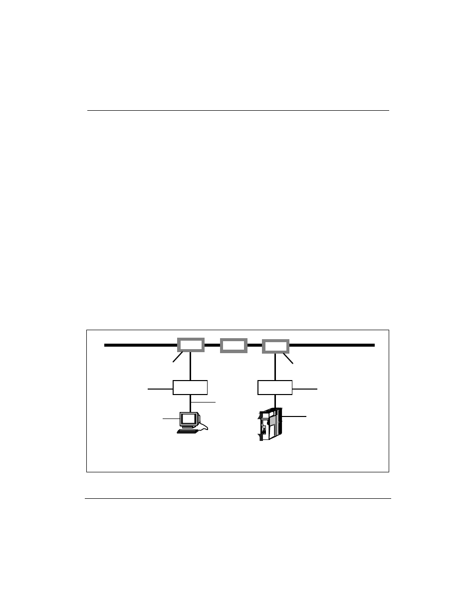
Before you install Ethernet LAN support on your IPE Module or
Application Module, you must ensure that you have the following customer-
supplied equipment installed (see Figure 76):
¥
an Ethernet backbone cable that connects all nodes together (a
LAN-attached PC and a LAN-attached host computer are examples of
nodes)
¥
two or more taps attached to the backbone for connecting nodes
¥
at least one Ethernet transceiver for connecting a node to a tap
(multiport transceivers, also called fan-out boxes, connect two or more
nodes to a tap)
¥
two or more nodes, each of which must have an Ethernet transceiver
interface in its CPU
¥
two or more drop cables for connecting nodes to transceivers (or
multiport transceivers to taps)
Note: IPE Modules and Application Modules have built-in Ethernet
interfaces.
Figure 76
Ethernet backbone terminology (example)
TP
Ethernet backbone
node (IPE Module
or Application Module)
tap
* An Application Module must be equipped with an MVME167 SBC card
and an MVME712M transition card.
transceiver box
drop cable
tap
transceiver box
node (PC)
(with an Ethernet
interface card)