Meridian America Link/Customer Controlled Routing User Manual
Page 293
Chapter 11: Peripheral device cabling interface 275
Meridian Link Release 5C/CCR Release 3C Installation and Upgrade Guide
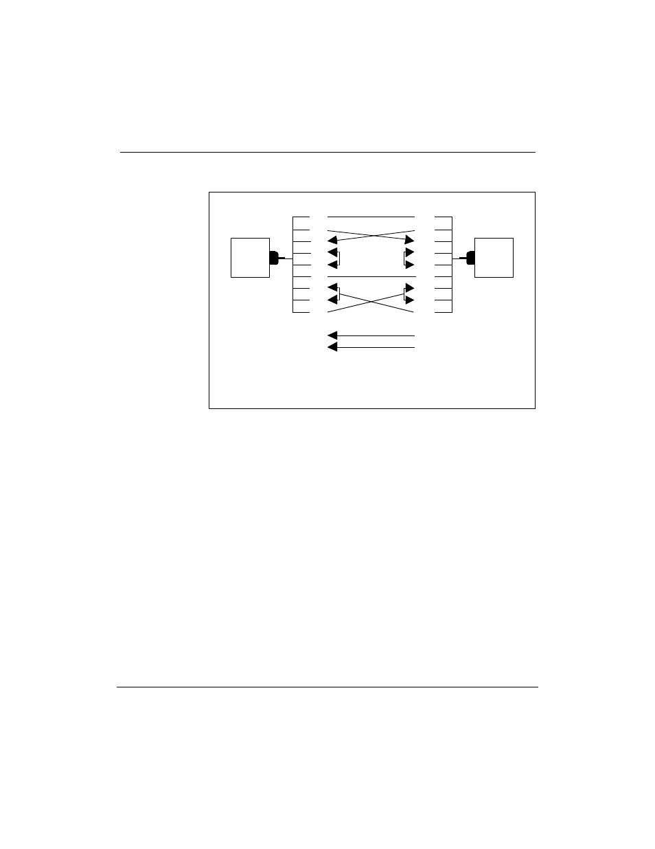
Figure 80
Null modem RS-232 cable
Pin
1
2
3
4
5
7
6
8
20
15
17
DTE
Pin
1
2
3
4
5
7
6
8
20
15
17
DTE
Note 1: This cable applies equally to a configuration with a
DCE device at each end.
Note 2: Pins 15 and 17 are used for some configurations.
The ports on the IPE Module can be configured as DCE or DTE using
connectors on the CPU adapter card. (For more information, refer to
ÒInstalling the IPE ModuleÓ in Chapter 8, ÒHardware installation
procedures.У)