Meridian America Link/Customer Controlled Routing User Manual
Page 310
292 Chapter 11: Peripheral device cabling interface
553-3202-210 Standard October 1998
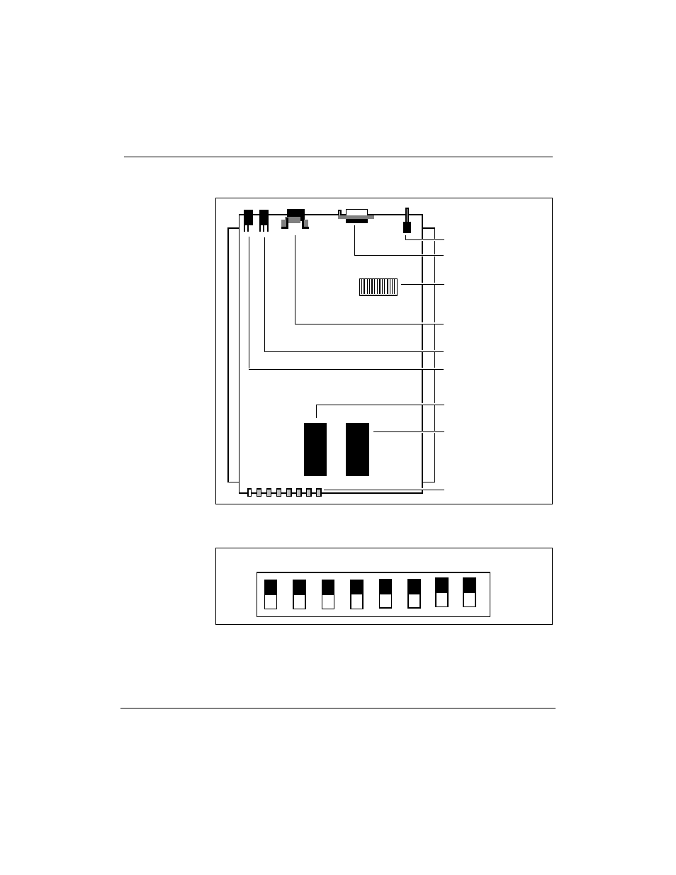
Figure 92
Ven-Tel 9600 Plus modemÑswitch locations and settings
¥
White and red
indicator lights
SW2 switch (red)
Line in
Line out
Power cable socket
RS-232/EIA socket
Power switch
¥
¥
¥
¥
¥
¥
¥
EPROM U14-O
EPROM U12-E
¥
Figure 93
Dial-up modemÑVen-Tel 9600 Plus modem SW2 switch settings
OFF
1
2
3
4
5
6
7
8
ON